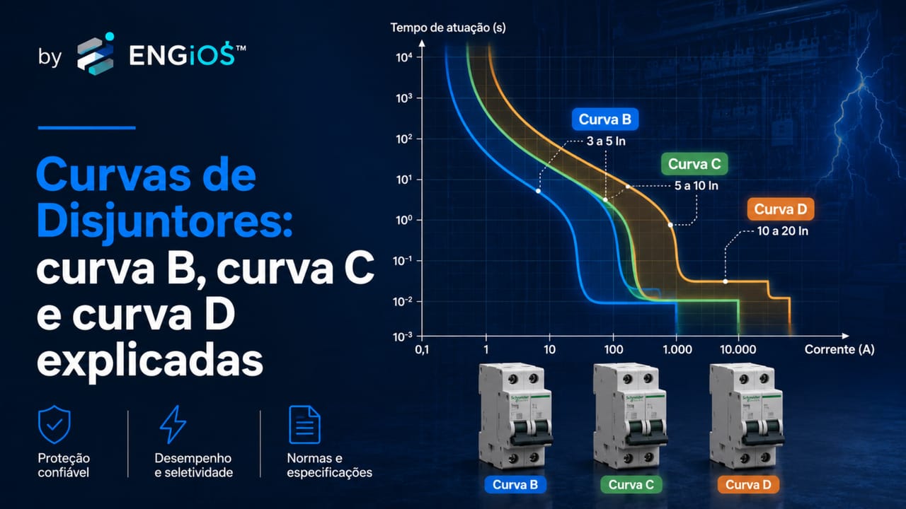
Understand circuit-breaker trip curves, the difference between Type B, Type C and Type D, and how proper selection depends on the load, starting current, NBR 5410 and electrical design.
Check it out!
Circuit-breaker trip curves indicate how a circuit breaker behaves when current rises above its rated current, especially in the magnetic operating region associated with short circuits and current peaks. In low-voltage electrical installations, the best-known curves are Type B, Type C and Type D.
The direct answer is: Type B trips magnetically at lower current multiples, Type C requires a higher trip current, and Type D tolerates even higher transient currents before magnetic operation. For this reason, choosing among B, C and D should not be based only on habit, brand or stock availability. It depends on the load, starting current, circuit impedance, prospective short-circuit current, conductor capacity and coordination with other protective devices.
In practical terms, the breaker curve helps answer an essential electrical-design question: should the breaker operate immediately at this current, or is this current part of the load’s normal behavior?
This difference is decisive in lighting circuits, socket-outlets, motors, transformers, equipment with electronic power supplies, air-conditioning, electrical panels, main low-voltage switchboards and industrial installations. A breaker with an unsuitable curve may trip without a real fault or, at the opposite extreme, delay operation during a fault that should be interrupted quickly.
What are circuit-breaker trip curves?
A circuit-breaker curve represents the relationship between the current flowing through the device and the time required for it to operate. In other words, it shows how the breaker responds to different current levels.
When current is only slightly above rated current, operation tends to occur through the breaker’s thermal element over a longer time. When current is very high, as in a short circuit, operation occurs through the magnetic element in a much shorter interval.
Types B, C and D differentiate magnetic operating ranges. They help match the breaker to load behavior. A purely resistive load does not behave the same way as a motor, transformer or equipment with high inrush current. Therefore, the same rated current may require different trip curves depending on the application.
Difference between Type B, Type C and Type D
The main difference between Type B, Type C and Type D lies in the current range that causes the breaker’s instantaneous magnetic operation.
In common applications of modular circuit breakers under product standards, the logic is as follows:
| Curve | Typical magnetic operating range | General application |
| Type B | approximately 3 to 5 times rated current | loads with low starting current |
| Type C | approximately 5 to 10 times rated current | loads with moderate starting current |
| Type D | approximately 10 to 20 times rated current | loads with high starting current |
These values should not be used as a substitute for design. They serve to explain the application logic. Final selection must consider the actual circuit, actual load, available short-circuit current and the characteristics of the specific device stated by the manufacturer.
The breaker curve must match the behavior of the load
The choice among Type B, C and D should be made within the complete specification of the protective device. For an overview of breaker types, functions and specification criteria, see Low-Voltage Circuit Breakers: types, function and specification criteria.
Breaker curve is not the same as amperage
A common mistake is to treat the breaker curve as merely another way of indicating amperage. That is incorrect.
The breaker’s rated current indicates the current the device can carry under normal conditions within the manufacturer’s specified limits. The trip curve indicates how the breaker reacts when current exceeds certain multiples of rated current.
For example, two 20 A breakers can behave differently if one is Type B and the other Type C. Both have the same rated current, but magnetic operation occurs in different ranges. This means they may respond differently to a starting current, a transient peak or a short-circuit condition.
Therefore, specifying a circuit breaker requires analyzing at least three dimensions: rated current, trip curve and breaking capacity. In more critical designs, selectivity, let-through energy, minimum and maximum short-circuit current, coordination with upstream and downstream devices and compatibility with RCDs and SPDs must also be considered.
How a thermomagnetic circuit breaker works
Most discussions about Type B, C and D curves relate to thermomagnetic circuit breakers. This type of breaker combines two operating mechanisms: thermal and magnetic.
Thermal operation is related to overloads. When current remains above the permissible value for a certain period, the thermal element responds to heating and opens the circuit.
Magnetic operation is associated with high currents over a short time. It is designed to respond quickly to fault currents or currents far above the circuit’s normal operating current.
Types B, C and D are mainly associated with the magnetic region. They indicate the current range that tends to cause rapid breaker operation. Therefore, the curve must match the load type. If the load has high starting current, a curve that is too sensitive may cause nuisance tripping. If the curve is too tolerant, magnetic operation may be delayed under certain fault conditions.
Thermal operation and magnetic operation
Thermal operation and magnetic operation should not be confused.
Thermal operation has inverse-time behavior: the higher the overload current, the shorter the operating time tends to be. It protects conductors against excessive heating caused by currents above the permissible value for a certain period.
Magnetic operation is much faster. It responds to high currents, normally associated with short circuits or intense current peaks. This is the region in which the difference between Type B, Type C and Type D becomes most evident.
In electrical design, these two operating regions must work together. The breaker must allow normal load operation, withstand expected transients, protect conductors against overload and interrupt short-circuit currents in a manner compatible with the installation.
What is a circuit-breaker operating curve?
An operating curve represents breaker behavior as a function of current and time. It shows under which conditions the device should operate and how long that operation takes.
In technical catalogs, this curve is usually presented as a time-current graph. The current axis is normally shown in multiples of rated current. The time axis shows the possible operating range.
This curve is important because an installation does not operate only in steady state. Motors start, transformers are energized, electronic power supplies charge capacitors, compressors start and equipment can produce transient peaks. The breaker must distinguish between a normal starting condition and a fault condition.
What is a circuit-breaker trip curve?
Trip curve is a common way of referring to the operating curve. In practice, when someone searches for “circuit breaker trip curve,” they usually want to understand at what current range the breaker trips.
The term “trip” is widely used in the field, but in design it is more precise to refer to operation, automatic disconnection or circuit opening. The central idea, however, is the same: understanding the relationship between current, time and device behavior.
For Types B, C and D, the main concern is usually magnetic operation. The objective is to prevent the breaker from operating unnecessarily during normal starting current while also ensuring that it operates correctly during a short-circuit current.
Type B curve: what it is and when to use it
A Type B circuit breaker has magnetic operation at a lower current range than Types C and D. In common applications, it tends to operate magnetically when current reaches approximately 3 to 5 times rated current.
This means it is more sensitive to high currents of short duration. This characteristic may be desirable in circuits with low starting current, predominantly resistive loads or circuits where the available short-circuit current at the farthest point is not very high.
Type B may be associated with loads such as resistive heating, circuits with low energization current and applications in which no significant initial peak is expected. However, its application must be verified within the design context.
A common mistake is to say that Type B is “weaker.” This interpretation is not appropriate. Type B is not necessarily inferior to Type C or D. It simply operates magnetically at a lower multiple of rated current. In some circuits, that is exactly the desired behavior.
When can Type B be unsuitable?
Type B can cause nuisance tripping when applied to loads with high starting current. Motors, transformers, compressors, equipment with robust switched-mode power supplies and loads with magnetizing current may momentarily exceed the Type B magnetic operating range during normal energization.
In these cases, replacing Type B with Type C or D may seem like a simple solution, but the change should not be made without analysis. The new curve must continue to ensure adequate short-circuit protection, including at the farthest point of the circuit.
Type C curve: what it is and when to use it
Type C circuit breakers are very common in building, commercial and light-industrial installations. Their magnetic operation occurs at a higher range than Type B, typically between 5 and 10 times rated current.
This characteristic allows moderate starting currents to be tolerated without nuisance operation. For this reason, Type C is frequently found in socket-outlet circuits, lighting with drivers, small motors, general-purpose equipment and loads with moderate transient behavior.
Type C is popular, but that does not mean it is automatically correct. In many panels it is adopted as a default out of habit. The problem is that an installation should not be specified by habit. It should be specified according to the load, circuit, conductor, design current, short-circuit current and protection coordination.
Why did Type C become so common?
Type C provides a practical balance for many low-voltage loads. It is less sensitive than Type B to transient peaks, but not as tolerant as Type D. This makes it suitable for many general-purpose circuits.
The risk is turning this balance into a universal rule. In long circuits with low available short-circuit current, Type C may not be the best solution. With loads that have very high starting current, Type C may still trip. In systems with critical selectivity, the curve must be analyzed together with upstream and downstream devices.
Type D curve: what it is and when to use it
A Type D circuit breaker has magnetic operation at a higher current range, typically between 10 and 20 times rated current. This means it tolerates higher transient currents before magnetic operation.
This characteristic may be necessary for loads with high starting current, such as motors, transformers, machinery, equipment with high energization current and certain industrial circuits.
Type D can reduce nuisance tripping during starting, but it requires greater technical attention. By tolerating higher currents before magnetic operation, it also requires the available short-circuit current to be sufficient to produce the expected operation under fault conditions.
Type D is not “better” than Type C
Type D is not a superior version of Type C. It is simply a different curve applied to loads with different behavior.
Using Type D to solve tripping without diagnosing the cause can be dangerous. Tripping may be related to actual overload, a load defect, intermittent short circuit, voltage drop, unsuitable starting method, incorrect circuit sizing or lack of coordination. Changing the curve without analysis can mask the problem and reduce protection effectiveness.
Comparison table: Type B, Type C and Type D
| Criterion | Type B | Type C | Type D |
| Magnetic sensitivity | Higher | Intermediate | Lower |
| Typical magnetic operating range | 3 to 5 In | 5 to 10 In | 10 to 20 In |
| Tolerated starting current | Low | Moderate | High |
| Typical application | resistive loads and low starting current | general use with moderate transients | motors, transformers and loads with high current peaks |
| Risk if misapplied | nuisance tripping | used as a default without verification | delayed or absent magnetic operation if Ikmin is low |
| Critical design point | avoid tripping during normal transients | verify it has not become an automatic choice | confirm minimum short-circuit current and coordination |
This table helps explain the general logic, but it does not replace technical analysis. In electrical design, the curve must be coordinated with the actual installation.
Starting current and nuisance tripping
Starting current is one of the main reasons different circuit-breaker curves exist. Many loads do not start by drawing only their rated current. During energization, they may demand higher transient currents.
Motors, transformers, compressors, switched-mode power supplies, luminaires with drivers, electronic equipment and machinery may present current peaks during startup or energization. These peaks may last only briefly, but they can be sufficient to cause magnetic operation if the breaker curve is incompatible.
This is why a circuit breaker may trip when the load starts even if the steady-state current is within the expected range. In these cases, the correct question is not simply “which breaker should I install?” but rather: what is the starting current, which curve is installed, what short-circuit current is available and what is the function of this circuit?
Tripping during startup does not always mean the breaker is defective
Recurring trips may indicate unaccounted-for starting current, overload, a sizing error or lack of protection coordination. To understand the analysis within electrical design, see Low-Voltage Electrical Designs: key stages and standards recommendations.
Resistive loads, inductive loads, motors and transformers
The nature of the load directly influences curve selection.
Resistive loads tend to have more predictable behavior and low starting current. In these cases, a more sensitive curve may be appropriate, provided the other protection criteria are met.
Inductive loads may have higher starting current. Motors, contactors, solenoids and transformers require attention because they can produce transient peaks during energization. Curve selection must consider this behavior.
Motors require specific analysis. Starting current may be several times higher than rated current. Depending on the starting method, mechanical load, duty and protection used, it may be necessary to use a motor circuit breaker, thermal overload relay, suitable magnetic protection or another coordinated solution.
Transformers may also present high magnetizing current during energization. In some cases, the transient current can cause nuisance operation of poorly selected circuit breakers.
Should Type C be used as the default?
No. Type C is common, but it should not be treated as an automatic default.
In many installations, it works adequately because many loads have moderate peaks. However, “working” is not the same as being technically verified. An installation may operate for years with unsuitable choices until a load expansion, circuit modification, equipment replacement or fault exposes the weakness of the protection.
The electrical design must verify that the selected curve meets both normal operating conditions and fault conditions. This includes load, starting current, design current, conductor cross-section, current-carrying capacity, short-circuit current, breaking capacity and selectivity.
What NBR 5410 says about overcurrent protection
ABNT NBR 5410 treats overcurrent protection as an essential requirement of low-voltage electrical installations. The standard requires live conductors to be protected by automatic disconnection devices against overloads and short circuits, subject to specific exceptions.
The standard also establishes that overload protection and short-circuit protection must be coordinated. This is important because a circuit breaker can protect against both conditions provided it is correctly selected and installed.
The objective is to interrupt overcurrents before their thermal and mechanical effects become dangerous or cause temperature rise that can damage insulation, connections, terminations and conductors.
This logic is the basis for addressing Types B, C and D. The curve is not an aesthetic or commercial preference. It is a device characteristic that must be compatible with the protection required by the circuit.
Coordination between conductors and protective devices
One of the central criteria of NBR 5410 is coordination between conductors and protective devices. The standard works with the relationship among design current, device rated current, conductor current-carrying capacity and conventional operating current.
In design terms, overload protection must follow this logic:
- the rated current or setting of the device must be compatible with the design current;
- the device must not allow the conductor to operate above its permissible capacity;
- operation must occur before heating compromises insulation and conductor service life.
This means Type B, C or D does not replace cable sizing. Before discussing the curve, it is necessary to know the design current, the current-carrying capacity of the conductors and the conditions under which those conductors are installed.
Relationship between breaker curve and minimum short-circuit current
NBR 5410 requires prospective short-circuit currents to be determined at the necessary points of the installation. This includes an often-overlooked issue: the minimum short-circuit current at the farthest point of the circuit.
In a long circuit, conductor impedance reduces the fault current available at the end of the line. If the minimum short-circuit current is low, a higher magnetic trip curve may not operate as expected.
This is especially relevant to Type D. Because it requires higher multiples of rated current for magnetic operation, its application must verify that the available short-circuit current will be sufficient to produce rapid operation in the event of a fault.
The same logic can affect Type C in certain circuits. In extensive installations, long feeders, remote panels or systems with low short-circuit power, the curve should not be selected without calculation.
Long circuits require attention to short-circuit current at the farthest point
In extensive circuits, conductor impedance can reduce the available fault current and affect magnetic breaker operation. This criterion should be evaluated together with the installation design. Also see the Complete Guide to Low-Voltage Electrical Installations.
Maximum short-circuit current and breaking capacity
In addition to minimum current, the maximum prospective short-circuit current at the circuit-breaker installation point must also be assessed.
The circuit breaker’s breaking capacity must be compatible with this current. Two breakers can have the same rated current and the same curve but different breaking capacities. In panels close to the origin of the installation, transformers or main feeders, this difference can be decisive.
A 32 A Type C circuit breaker, for example, is not a complete specification. Its breaking capacity, product standard, number of poles, operating voltage, application, coordination with adjacent devices and conditions at the installation point must also be known.
Joule integral and let-through energy
In short circuits, it is not enough to know whether the circuit breaker operates. It also matters how much energy passes through the circuit before opening.
NBR 5410 addresses the relationship between the energy let through by the protective device and the energy the conductor can withstand without damage. This concept is associated with the Joule integral, often represented as I²t.
In practical terms, the higher the current and the longer the operating time, the greater the thermal energy applied to conductors and components. The circuit breaker must limit this energy to a level compatible with the withstand capability of the protected conductor.
This is a more advanced topic, but it is essential in industrial installations, main switchboards, electrical panels, higher-current circuits and systems in which protection must be technically coordinated.
Relationship among curve, conductor cross-section and circuit length
The circuit-breaker curve cannot be analyzed independently of conductor cross-section and circuit length.
Conductor cross-section affects current-carrying capacity and thermal withstand. Length affects voltage drop and circuit impedance. Impedance, in turn, affects the short-circuit current available at the farthest point.
Therefore, in long circuits, it is not enough to verify that the load operates normally. It is necessary to confirm that a fault at the end of the circuit will produce sufficient current for proper operation of the protective device.
This analysis is one reason field replacements should be handled carefully. Replacing a breaker with one having a different curve can change protection behavior without the rest of the circuit having been reassessed.
Selectivity between circuit breakers
Selectivity is the ability to ensure that, in the event of a fault, only the device responsible for the affected circuit operates, keeping the other circuits energized whenever possible.
NBR 5410 addresses selectivity when safety or continuity-of-service requirements demand that the installation not be disconnected beyond what is necessary. In commercial, industrial, healthcare and educational installations, data centers, condominiums, security systems and critical infrastructure, this can be highly relevant.
The circuit-breaker curve influences this analysis because it changes the device’s time-current behavior. In an installation with a main breaker, distribution panels and final circuits, curve selection must consider coordination among devices connected in series.
In main switchboards and panels, breaker curves should be analyzed together with selectivity
When devices are connected in series, curve selection influences protection coordination and continuity of service. To connect this subject with electrical infrastructure as a system, see Low-Voltage Electrical Installations.
Relationship between breaker curves, RCDs and SPDs
Types B, C and D concern circuit-breaker behavior under overcurrent conditions. They should not be confused with RCD types such as Type AC, Type A or Type B.
The circuit breaker protects against overload and short circuit. The RCD operates on residual currents, contributing to protection against electric shock and certain types of earth fault. The SPD protects against transient overvoltages and must be coordinated with overcurrent protection according to the installation and manufacturer instructions.
In actual electrical panels, these devices coexist. Selection of the breaker curve should be part of an integrated protection approach, not an isolated decision.
Type B, Type C and Type D in socket-outlet circuits
Socket-outlet circuits can supply very different loads. A socket-outlet may supply a small charger, an electronic power supply, a tool, motor-driven equipment, a UPS or equipment with high energization current.
Therefore, it is not technically correct to state that every socket-outlet circuit must always use one specific curve. Selection depends on the circuit purpose, expected load type, design current, installation method and other system conditions.
In general-purpose circuits, Type C appears frequently, but this does not eliminate the need for analysis. When dedicated circuits supply specific equipment, the curve should be selected based on the equipment and the design.
Types B, C and D in lighting circuits
Lighting circuits have also changed significantly with the use of drivers, electronic power supplies and LED luminaires. In many installations, steady-state current is low, but energization current can be significant depending on the number of luminaires and type of driver.
This can cause tripping during energization, especially when many points are switched on simultaneously. The solution should not simply be to increase the breaker’s rated current or change the curve by trial and error. Starting current must be assessed, circuits divided when necessary, conductors checked and adequate protection ensured.
Circuit-breaker curve for motors
Motors are loads that require special attention. Starting current may be several times higher than rated current, and starting time depends on the motor, mechanical load and starting method.
In some cases, a motor circuit breaker or a specific protection assembly may be used, considering overload, short circuit, coordination with the contactor, thermal overload relay and operating duty.
Type D may appear in situations with high starting current, but it should not be adopted automatically. The design must ensure that short-circuit protection remains effective and that the conductors are protected.
Circuit-breaker curve for transformers
Transformers can present high magnetizing current during energization. This initial peak may cause nuisance operation if the circuit breaker is not compatible with the load behavior.
In these applications, curve selection should be based on transformer characteristics, rated current, energization current, available short-circuit power, upstream protection and selectivity.
Type D may be considered in some cases, but always with technical verification. Simply changing the curve to avoid tripping may compromise operation under lower-current fault conditions.
Circuit-breaker curve for air-conditioning
Air-conditioning equipment may have significant starting behavior, especially compressors and non-inverter equipment. Modern equipment with power electronics may also have specific energization-current characteristics.
Circuit-breaker selection should consider manufacturer data, operating current, starting current, conductors, distance, installation method and recommended protection. The curve should not be selected only by a generic rule.
In commercial installations with multiple units, circuit grouping and simultaneity must also be considered.
Common mistakes when choosing a circuit-breaker curve
The most common mistakes are:
- using Type C as a universal default;
- replacing Type B with Type C without analyzing the cause of tripping;
- replacing Type C with Type D to “stop tripping”;
- choosing the curve only by load type without checking short-circuit current;
- ignoring circuit length;
- ignoring breaking capacity;
- confusing a Type B circuit-breaker curve with a Type B RCD;
- increasing circuit-breaker rated current to avoid tripping;
- failing to assess selectivity;
- disregarding guidance from the load or protective-device manufacturer.
In all these cases, the risk is treating the symptom rather than the cause. A trip may indicate protection operating correctly, actual overload, a load defect, unaccounted-for starting current, intermittent short circuit, leakage, heating, connection failure or a design error.
How to choose between Type B, Type C and Type D
Curve selection should follow a technical sequence.
First, define the load and its design current. Then verify conductor current-carrying capacity, installation method, cable cross-section, voltage drop and grouping and temperature conditions.
Next, evaluate load behavior during starting or energization. If the load has low starting current, a more sensitive curve may be appropriate. If it has moderate starting current, Type C may be considered. If it has high starting current, Type D or a specific solution may be necessary.
Then verify the maximum prospective short-circuit current at the installation point and the breaker’s breaking capacity. The minimum short-circuit current at the farthest point must also be checked to confirm proper operation.
Finally, assess coordination with upstream and downstream devices, selectivity, compatibility with RCDs and SPDs, continuity-of-service requirements and technical documentation.
Practical specification sequence
An appropriate sequence for specifying a circuit-breaker curve can be summarized as follows:
1. identify the load and its function in the system; 2. determine the circuit design current; 3. size conductors according to the installation method; 4. verify voltage drop; 5. evaluate starting or energization current; 6. select circuit-breaker rated current according to the circuit; 7. choose the operating curve compatible with the load; 8. verify breaking capacity; 9. verify minimum short-circuit current at the farthest point; 10. verify let-through energy and conductor withstand where applicable; 11. assess selectivity and coordination; 12. record the specification in the design, design narrative, single-line diagram and panel documentation.
Want to turn protection criteria into a verifiable technical specification?
The selected curve should appear in the design, design narrative, single-line diagram, panel documentation and maintenance criteria. To move from conceptual explanation to engineering application, see Low-Voltage Electrical Designs.
When should specialized engineering be engaged?
Specialized engineering is recommended when there is recurring tripping, heating in panels, load expansion, equipment replacement, installation of motors, transformers, air-conditioning, machinery, main low-voltage switchboards, electrical panels, renovation of installations or a need to comply with NBR 5410.
It is also indicated when there is no updated single-line diagram, when the installation has undergone successive expansions, when circuit breakers have been replaced by trial and error or when operational continuity is relevant.
Technical analysis makes it possible to verify whether the installed curve is appropriate, whether conductors are protected, whether the short-circuit current is compatible, whether breaking capacity is sufficient and whether the devices are coordinated.
Deepen your knowledge of circuit-breaker curves and sizing
Curve selection should be integrated into the complete design criteria. See the white paper Method for Specification and Sizing of Circuit Breakers in Low-Voltage Electrical Installations and complement the analysis with the eBook Electrical Grounding: Fundamentals, Design and Standardization.
Conclusion
Circuit-breaker curves are not merely catalog details. They indicate device behavior under high currents and directly influence overcurrent protection, tolerance to starting currents and operation under short-circuit conditions.
Type B tends to be applied to loads with low starting current. Type C is common for general-purpose loads and moderate starting current. Type D is associated with loads with high starting current, such as motors, transformers and certain industrial applications. None is universally better.
Correct selection depends on the load, conductors, design current, prospective short-circuit current, breaking capacity, energy withstand, selectivity and coordination with other devices.
For this reason, the circuit-breaker curve should be treated as part of the electrical design, not as an isolated decision made when purchasing or replacing a component.
Technical references
[1] ASSOCIAÇÃO BRASILEIRA DE NORMAS TÉCNICAS. ABNT NBR 5410 — Low-voltage electrical installations. Consult the ABNT Catalog to confirm the current edition and amendments.
[2] ASSOCIAÇÃO BRASILEIRA DE NORMAS TÉCNICAS. ABNT NBR NM 60898 — Circuit breakers for overcurrent protection for household and similar installations.
[3] INTERNATIONAL ELECTROTECHNICAL COMMISSION. IEC 60898-1:2015+AMD1:2019 — Circuit-breakers for overcurrent protection for household and similar installations.
[4] ASSOCIAÇÃO BRASILEIRA DE NORMAS TÉCNICAS. ABNT NBR IEC 60947-2 — Low-voltage switchgear and controlgear — Circuit-breakers.
[5] INTERNATIONAL ELECTROTECHNICAL COMMISSION. IEC 60947-2:2024 — Low-voltage switchgear and controlgear — Part 2: Circuit-breakers.
[6] ASSOCIAÇÃO BRASILEIRA DE NORMAS TÉCNICAS. ABNT NBR 5361 — Low-voltage circuit breakers.
Frequently asked questions
Circuit-breaker curves indicate device behavior at currents above rated current, especially in the magnetic operating region associated with short circuits and transient peaks.
The difference lies in the current range that causes magnetic operation. Type B operates at lower current multiples, Type C at an intermediate range and Type D at higher transient currents.
A Type B circuit breaker is used for loads with low starting current, provided the circuit protection criteria are satisfied.
A Type C circuit breaker is common in general-purpose circuits and loads with moderate starting current, but it should not be used automatically without circuit analysis.
A Type D circuit breaker is applied to loads with high starting current, such as motors, transformers and certain machines, provided the available short-circuit current is compatible.
No. Type C is not better than Type B. It simply has a different magnetic operating range. Selection depends on the load, starting current and circuit.
No. Type D tolerates higher transient currents, but it may be unsuitable if the minimum short-circuit current is insufficient to produce adequate magnetic operation.
It is the relationship between current and circuit-breaker operating time. It shows under which conditions the device opens the circuit.
It is a common term for the operating curve, indicating the current range in which the breaker tends to trip.
Not without technical analysis. Tripping may indicate incompatible starting current, overload, a fault, an intermittent short circuit or a sizing error.
Changing to Type D should only be done after checking the load, starting current, minimum short-circuit current, breaking capacity and coordination with other devices.
NBR 5410 addresses overcurrent protection and device selection. Types B, C and D are operating characteristics defined in circuit-breaker product standards.
Motors may require a curve compatible with starting current or specific devices such as a motor circuit breaker. Selection depends on the motor, starting method, mechanical load and design.
There is no single mandatory curve for socket-outlets. Selection depends on the expected load, starting current, conductors, circuit length and required protection.
It depends on the equipment, operating current, starting current, manufacturer data, conductors and circuit distance. It should not be defined by a generic rule alone.
Additional technical materials
Related solutions
- Low-Voltage Electrical Infrastructure
- Main Low-Voltage Switchboards and Low-Voltage Electrical Panels
- Electrical Safety and NR-10 Compliance
Related engineering services
- Low-Voltage Electrical Design
- Short-Circuit, Selectivity and Protection Coordination Study
- Electrical Installation Inspection
- Commissioning and Technical Acceptance of Electrical Installations
Related technical content
- Low-Voltage Circuit Breakers
- Thermomagnetic Circuit Breaker
- Motor Circuit Breaker
- Breaking Capacity: Icu and Ics
- Circuit-Breaker Selectivity
- How to Size Circuit Breakers
- Electrical Cable Sizing
