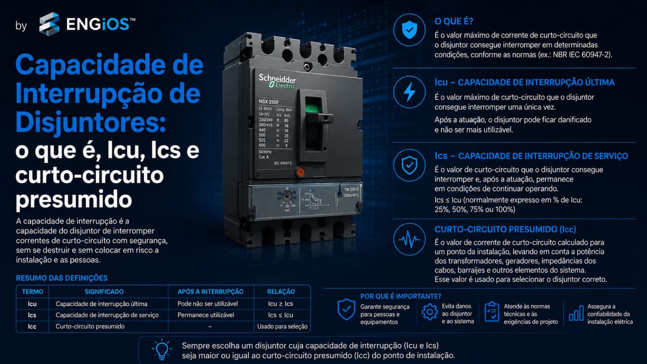
Understand circuit-breaker breaking capacity, what kA, Icu and Ics mean, and how to compare the device with prospective short-circuit current according to NBR 5410.
Check it out!
Circuit-breaker breaking capacity is the short-circuit current a circuit breaker can safely interrupt at the point where it is installed, according to the conditions declared by the product standard and manufacturer.
The direct answer is: the circuit breaker’s breaking capacity must be compatible with the prospective short-circuit current at the installation point. If the prospective short-circuit current in a panel is higher than the device breaking capacity, the specification is inadequate unless technically proven coordination with an upstream device exists.
This criterion is different from rated current. Rated current indicates circuit operating current, such as 32 A, 100 A or 250 A. Breaking capacity, normally expressed in kA, concerns the fault current the breaker can interrupt. In low-voltage systems, this distinction is essential in distribution boards, main low-voltage switchboards, electrical panels, feeders, molded-case circuit breakers and main breakers.
What is circuit-breaker breaking capacity?
Breaking capacity is the circuit breaker’s ability to interrupt a short-circuit current within specified limits. It is defined by the product standard and manufacturer testing.
During a short circuit, current can be much higher than normal circuit current. The protective device must interrupt this current in a manner compatible with the electrical system, conductors and the other installation components.
Therefore, breaking capacity should not be treated as a catalog detail. It is part of safety, standards compliance and protection-system reliability.
Breaking capacity is not rated current
Rated current indicates the circuit breaker’s service current. It is used to coordinate the device with the load and conductor current-carrying capacity.
Breaking capacity indicates the short-circuit current the device can interrupt. It is expressed in kiloamperes, such as 6 kA, 10 kA, 25 kA, 36 kA or 50 kA.
A 32 A circuit breaker may have a 6 kA breaking capacity. Another 32 A breaker may have a 10 kA breaking capacity. Both have the same rated current but do not necessarily have the same application.
| Criterion | What it indicates | Example |
| Rated current | circuit operating current | 32 A, 63 A, 250 A |
| Breaking capacity | short-circuit current the breaker can interrupt | 6 kA, 10 kA, 25 kA |
| Trip curve or setting | operating behavior under overcurrent | Type B, C, D or electronic setting |
| Operating voltage | condition under which performance is declared | 220 V, 380 V, 400 V, 690 V |
Amperage and breaking capacity are different criteria
Before defining the breaker’s kA rating, its function, rated current, curve, poles and circuit application must be understood. Also see Low-Voltage Circuit Breakers: types, function and specification criteria.
What does kA mean on a circuit breaker?
kA means kiloampere. One kiloampere equals 1,000 amperes. When a breaker is marked 6 kA, this means its declared breaking capacity is 6,000 A under the conditions established by the manufacturer.
This does not mean the breaker carries 6,000 A during normal operation. Under normal conditions, it carries the rated current for which it was selected. The kA value refers to short-circuit performance.
This distinction is important because many specification errors result from confusing circuit amperage with breaking capacity.
6 kA, 10 kA, 25 kA and 50 kA circuit breakers: what is the difference?
The difference lies in the short-circuit current level the device can interrupt. Breakers rated 6 kA and 10 kA are common in many distribution boards and final circuits. Breakers rated 25 kA, 36 kA, 50 kA or more are common in more robust applications such as molded-case breakers, main low-voltage switchboards, panels and feeders.
Selection should not follow a fixed rule. A panel close to the transformer may have a higher prospective short-circuit current. A distant panel may have a lower value. Therefore, the installation point changes the analysis.
What is prospective short-circuit current?
Prospective short-circuit current is the current that could flow if a short circuit occurred at a specific point of the installation, considering the source, transformer, cables, busbars and system impedances.
NBR 5410 requires prospective short-circuit currents to be determined at points considered necessary by calculation or measurement. This information is the basis for selecting circuit-breaker breaking capacity.
In electrical design, this analysis may consider transformer power and impedance, voltage, feeder length, cable cross-section, conductor material and system configuration.
Maximum and minimum short-circuit current
Maximum short-circuit current is used to verify whether the breaker can interrupt the fault at the point where it is installed.
Minimum short-circuit current is used to verify whether the device can operate at the most unfavorable point of the protected line. On long feeders, for example, current at the circuit end may be lower than at the origin.
Therefore, short-circuit protection is not only about selecting a high kA value. It also involves verifying operation, coordination and conductor protection.
What does NBR 5410 require for breaking capacity?
NBR 5410 establishes that devices intended for short-circuit protection must have a breaking capacity at least equal to the prospective short-circuit current at the point where they are installed.
The standard permits a device with lower breaking capacity only when there is an upstream device with sufficient capacity and suitable coordination between the devices so that the let-through energy does not exceed what the downstream device and protected circuits can withstand.
This condition requires technical analysis. It is not a general authorization to use breakers below the prospective short-circuit level.
Prospective short-circuit current determines device selection
In main switchboards, panels and feeders, breaking capacity must be compared with the actual installation point. To see this criterion applied to robust devices, see Molded-Case Circuit Breaker: what it is, applications and specification criteria.
What is Icu?
Icu is the ultimate short-circuit breaking capacity defined in product standards applicable to low-voltage circuit breakers.
This parameter is common in breakers complying with ABNT NBR IEC 60947-2, especially molded-case and industrial circuit breakers. It indicates a limiting breaking capacity under specified test conditions.
The Icu value must be read together with operating voltage. The same breaker may have different capacities at different system voltages.
What is Ics?
Ics is the service short-circuit breaking capacity. It indicates circuit-breaker performance under a short-circuit condition associated with continued use according to the product-standard criteria.
In catalogs, Ics may be shown as a percentage of Icu, such as 25%, 50%, 75% or 100%, depending on the manufacturer’s product line.
In main switchboards, panels and feeders, Ics can be as important as Icu because the device is part of an installation that must remain safe, documented and operational.
Difference between Icu and Ics
Icu is the ultimate breaking capacity. Ics is the service breaking capacity. The difference lies in the performance considered after interruption and in the criteria defined by the product standard.
| Parameter | Practical interpretation | Use in specification |
| Icu | ultimate breaking capacity | checks the declared breaker limit |
| Ics | service breaking capacity | assesses service performance |
| kA | short-circuit current unit | compares the device with prospective short-circuit current |
| Voltage | application condition | verifies whether the kA value applies to the system |
In larger installations, especially with molded-case circuit breakers, Icu and Ics should be read from the technical catalog and recorded in the specification criteria.
Breaking capacity of DIN-rail circuit breakers
DIN-rail circuit breakers, or modular miniature circuit breakers, are common in final circuits. Depending on product line and product standard, they may have breaking capacities such as 3 kA, 4.5 kA, 6 kA or 10 kA.
They may be suitable in many distribution boards, but they should not be applied at points with a short-circuit level above their capacity without technical analysis.
In commercial installations, panels close to the service entrance, robust circuits or short feeders from a transformer, breaking capacity should be checked carefully.
Breaking capacity of molded-case circuit breakers
Molded-case circuit breakers normally offer higher breaking capacities and different trip-unit options. The same rated current is commonly available in product lines with different Icu and Ics values.
This means two 250 A breakers may have very different applications. Rated current is the same, but breaking capacity, settings, applicable voltage and coordination may differ.
In main low-voltage switchboards, industrial panels and feeders, molded-case circuit-breaker breaking capacity should be defined from the prospective short-circuit current at the installation point.
Breaking capacity in main low-voltage switchboards and electrical panels
Main low-voltage switchboards and main panels are often located near the origin of the installation. This can increase the prospective short-circuit current.
In these cases, circuit-breaker breaking capacity should be analyzed together with the panel assembly: busbars, conductors, upstream devices, downstream devices, assembly withstand current and selectivity requirements.
The specification should avoid incomplete descriptions such as “250 A main breaker.” For panels, rated current, breaking capacity, poles, voltage, trip unit, function, settings and coordination should be stated.
Joule integral and let-through energy
The Joule integral, often represented by I²t, is a way to assess thermal energy associated with current over time. In short-circuit protection, it helps verify whether the energy let through by the device is compatible with conductor withstand.
NBR 5410 uses this logic by relating the let-through energy of the protective device to conductor withstand, considering material, cross-section and insulation.
In practical terms, it is not enough for the breaker to interrupt. Operation must be compatible with the conductors and the devices involved.
Icu, Ics and let-through energy should be part of the specification criteria
When protection involves molded-case circuit breakers, main switchboards and feeders, technical documentation should record short-circuit and coordination criteria. See how this topic connects to Low-Voltage Electrical Designs.
Selectivity and breaking capacity
Selectivity is coordination among devices connected in series so that, when a fault occurs, the device closest to the affected point operates preferentially.
Breaking capacity and selectivity are related but different topics. A breaker may have adequate breaking capacity and still fail to provide selectivity. Selectivity depends on curves, settings, trip units, operating time and manufacturer tables.
NBR 5410 addresses selectivity when safety or utilization reasons require continuity of service. In commercial and industrial installations, this analysis can be decisive.
Cascading, backup and coordination between circuit breakers
Manufacturer catalogs may use concepts such as cascading, back-up protection or backup. They indicate the possibility of coordinating an upstream device with a downstream device under tested or documented conditions.
This application depends on manufacturer tables, compatible devices and specific conditions. It should not be improvised by mixing models without evidence.
When correctly applied, coordination can enable viable panel solutions. When applied without technical criteria, it can compromise protection.
Relationship with RCDs, RCBOs and SPDs
Breaking capacity also affects devices associated with RCDs, RCBOs and SPDs.
When an RCD incorporates or is associated with overcurrent protection, the assembly must comply with short-circuit protection criteria. When the RCD does not incorporate this protection, a suitable device must protect it.
An SPD may also require associated overcurrent protection to clear internal faults. Selection of that device must comply with SPD manufacturer requirements, prospective short-circuit current and the continuity-of-service strategy.
Deepen your knowledge of circuit-breaker specification and sizing
Breaking capacity is one of the sizing checks. To integrate kA, Icu, Ics, prospective short-circuit current, curves, conductors, selectivity, RCDs and SPDs into a single design criterion, see the white paper Method for Specification and Sizing of Circuit Breakers in Low-Voltage Electrical Installations. To deepen the basis of grounding, equipotential bonding and associated protection, also see the eBook Electrical Grounding: Fundamentals, Design and Standardization.
Common mistakes when selecting breaking capacity
The most common mistakes are:
- confusing rated current with breaking capacity;
- selecting a breaker only by amperage;
- ignoring the kA rating;
- using a 6 kA breaker where prospective short-circuit current is higher;
- using 10 kA as a universal rule;
- not calculating prospective short-circuit current;
- not checking the voltage associated with the kA rating;
- ignoring Icu and Ics in molded-case circuit breakers;
- not assessing let-through energy;
- assuming selectivity without a curve or manufacturer table;
- replacing a breaker with a supposedly equivalent model without checking breaking capacity;
- not updating the single-line diagram after changes.
These mistakes can compromise installation safety and compliance.
How to specify breaking capacity in electrical design
The specification should record:
- circuit-breaker rated current;
- breaking capacity at operating voltage;
- applicable product standard;
- prospective short-circuit current at the point;
- Icu and Ics, where applicable;
- trip curve or trip unit;
- number of poles;
- location in the single-line diagram;
- coordination with upstream and downstream devices;
- selectivity requirements;
- manufacturer or equivalent characteristics;
- setting and maintenance notes.
A specification such as “32 A breaker” or “250 A breaker” is incomplete. Even “250 A, 25 kA breaker” may be insufficient if voltage, poles, trip unit, function and expected coordination are not stated.
Breaking capacity should be treated as part of the electrical system
Selectivity, SPDs, RCDs, main breakers, feeders and boards must be coordinated. To connect this subject to the complete engineering solution, see Low-Voltage Electrical Installations.
When should specialized engineering be engaged?
Specialized engineering is recommended when there are main low-voltage switchboards, electrical panels, feeders, on-site transformers, load expansion, replacement of main breakers, recurring trips, SPD installation, RCDs, motors, variable-frequency drives, machinery or missing up-to-date electrical documentation.
It is also recommended when there is no short-circuit study, when the single-line diagram is outdated or when the installation must be brought into compliance with NBR 5410 and NR-10.
Technical analysis makes it possible to determine prospective short-circuit currents, verify breaking capacity, assess selectivity, confirm let-through energy and document protection criteria.
Conclusion
Breaking capacity is one of the most important criteria in circuit-breaker specification. It indicates the short-circuit current the device can safely interrupt and must be compatible with the actual installation point.
Correct selection requires comparing the circuit breaker with the prospective short-circuit current and considering operating voltage, Icu, Ics, let-through energy, selectivity and coordination with upstream and downstream devices.
In low-voltage installations, this subject should not be treated as a purchasing detail. It is part of electrical safety, standards compliance and protection-system reliability.
Technical references
[1] ABNT. NBR 5410:2004 — Low-voltage electrical installations.
[2] IEC. IEC 60947-2:2024 — Low-voltage switchgear and controlgear — Part 2: Circuit-breakers.
[4] ABNT. NBR IEC 61439-1 — Low-voltage switchgear and controlgear assemblies — General rules.
Frequently asked questions
It is the short-circuit current the circuit breaker can safely interrupt under the conditions specified by the product standard and manufacturer.
No. Rated current is the circuit operating current. Breaking capacity is the short-circuit current the circuit breaker can interrupt.
kA means kiloampere. On a circuit breaker, it indicates short-circuit breaking capacity, such as 6 kA, 10 kA or 25 kA.
The difference is the short-circuit current the device can interrupt. A 10 kA breaker has higher breaking capacity than a 6 kA breaker under the declared conditions.
Determine the prospective short-circuit current at the installation point and select a circuit breaker with compatible breaking capacity.
It is the current that could flow if a short circuit occurred at a specific point of the installation, considering source, transformer, cables, busbars and impedances.
NBR 5410 requires prospective short-circuit currents to be determined at the points considered necessary, by calculation or measurement.
Icu is the ultimate short-circuit breaking capacity declared according to the product standard for specified test conditions.
Ics is the service short-circuit breaking capacity, related to breaker performance under short-circuit conditions according to the product-standard criteria.
Icu represents ultimate breaking capacity. Ics represents service breaking capacity.
As a general rule, no. An exception is possible only when proven coordination with an upstream device exists.
It is the thermal energy associated with current flow over a certain time, normally represented by I²t.
Yes. It indicates the energy that passes through the device before complete short-circuit interruption and must be compatible with associated conductors and devices.
It is related to coordination but is not the same as selectivity. Selectivity depends on curves, settings and characteristics of devices connected in series.
Yes, especially in main low-voltage switchboards, panels, feeders and applications with high prospective short-circuit current.
It should be defined by a qualified professional based on the electrical design, prospective short-circuit current, applicable standards and manufacturer data.
Additional technical materials
Related solutions
- Main Low-Voltage Switchboards and Low-Voltage Electrical Panels
- Low-Voltage Electrical Infrastructure
- Electrical Safety and NR-10 Compliance
Related engineering services
- Short-Circuit, Selectivity and Protection Coordination Study
- Low-Voltage Electrical Design
- Electrical Installation Inspection
- Commissioning and Technical Acceptance
Related technical content
- Molded-Case Circuit Breaker
- Circuit-Breaker Selectivity
- How to Size Circuit Breakers
- Main Low-Voltage Switchboard: function, components and specification
- NBR IEC 61439 for Main Switchboards and Panels
