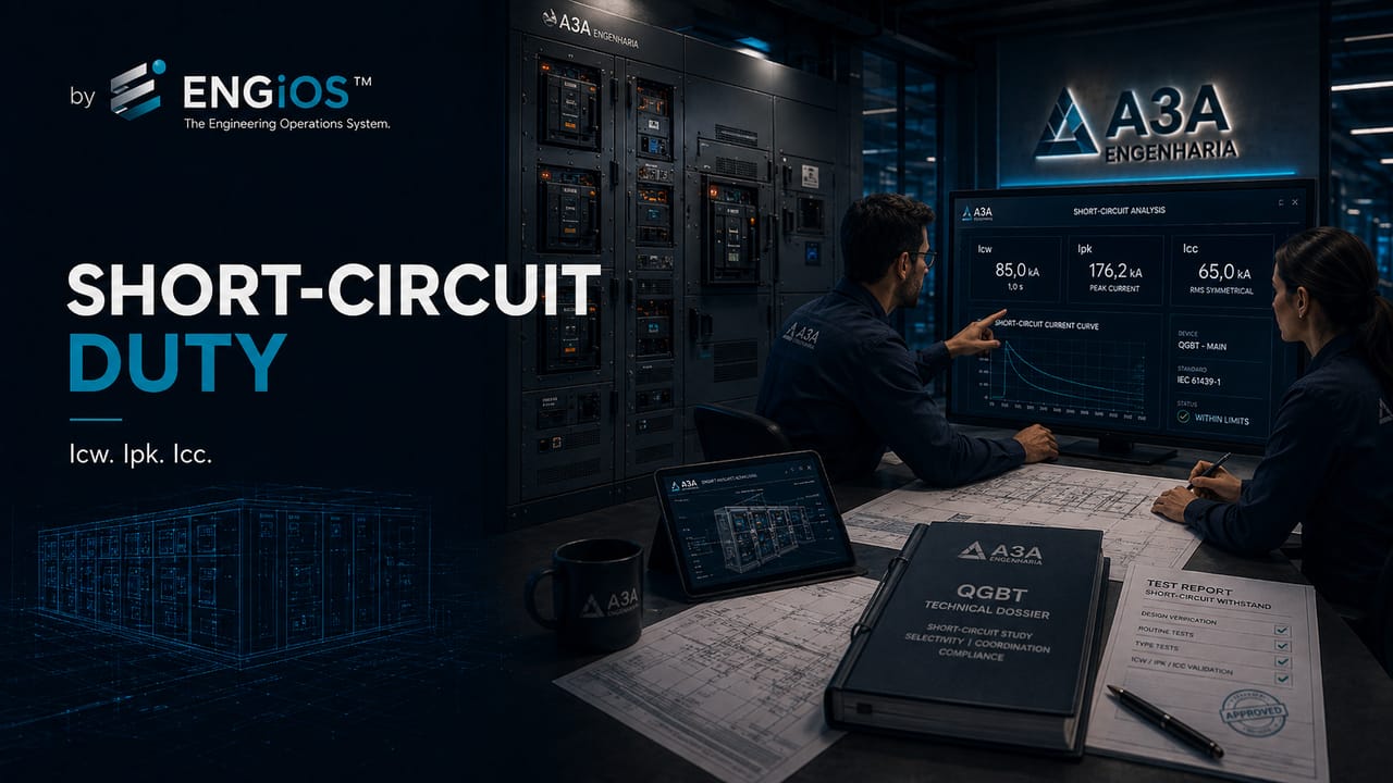
Understand Icw, Ipk and Icc in main low-voltage switchboards, the differences from circuit-breaker Icu and Ics, and how to specify assembly short-circuit withstand.
Check it out!
Icw, Ipk and Icc are short-circuit parameters applicable to main low-voltage switchboards and other low-voltage assemblies. The direct answer is: Icw represents the rms current withstand for a declared time, Ipk represents the peak current withstand, and Icc represents the conditional short-circuit current when performance depends on a specified protective device.
These quantities describe the behavior of the complete assembly and should not be confused with Icu and Ics, which characterize the breaking capacity of the circuit breaker. A circuit breaker capable of interrupting the fault does not, by itself, demonstrate that busbars, supports, connections, enclosure and protective circuit can withstand its effects.
Understanding these values is essential to verify whether the assembly can withstand the thermal and electrodynamic stresses associated with a fault at the point where it will be installed.
Why is short circuit critical in a main low-voltage switchboard?
The main low-voltage switchboard is often located close to the origin of the installation, frequently immediately downstream of a transformer or service entrance. At this position, the impedance between source and board may be low and the available short-circuit current may be high.
During a fault, the assembly is subjected to:
- intense heating over a short interval;
- electrodynamic forces between conductors and busbars;
- stresses on supports and connections;
- electric-arc formation;
- internal pressure on the enclosure;
- stress on protective devices.
The assessment cannot be limited to the main circuit breaker. Busbars, connections, supports, internal conductors, the protective circuit and enclosure must also have compatible performance.
What is prospective short-circuit current?
Prospective short-circuit current is the current that could flow at a given point if a fault with negligible impedance occurred.
At the main switchboard incoming point, this current may be represented by Icp. Its value depends on factors such as:
- transformer power and impedance;
- supply-network characteristics;
- cable length and cross-section;
- busbar and connection impedance;
- number of sources operating in parallel;
- contribution from motors and other rotating loads.
The designer should provide the assembler with the value applicable at the assembly connection point and record the calculation conditions, sources considered, voltage, equivalent impedance and expected fault-clearing time.
What is Icw?
Icw is the rated short-time withstand current of the assembly for a specified time.
It represents the assembly’s ability to withstand the thermal and dynamic effects of a short-circuit current during the declared interval, such as 0.2 s, 1 s or 3 s.
An isolated Icw value is incomplete without the associated time. Stating only “Icw 50 kA” does not indicate how long that current can be withstood. Thermal stress is related to both current and fault duration.
Icw is especially relevant when the protection strategy permits time delay on the main circuit breaker to obtain selectivity with downstream devices.
What is Ipk?
Ipk is the rated peak withstand current.
While Icw is related to the rms current over a specified time, Ipk represents the instantaneous peak that produces the greatest electrodynamic stresses on busbars, supports and connections.
The peak current can be significantly higher than the rms value because it includes the asymmetrical component of the fault. Its value depends on the resistance-to-reactance ratio of the circuit and should not be estimated simply by multiplying the rms current by √2.
Therefore, the mechanical design of the assembly must withstand the resulting forces without displacement, deformation, reduced insulation clearances or support failure. Verification involves busbar arrangement, phase spacing, geometry, fixing points and mechanical strength of the connections.
What is Icc?
Icc is the rated conditional short-circuit current of the assembly.
This parameter is used when the assembly short-circuit withstand depends on the operation of a defined short-circuit protective device, such as an upstream circuit breaker or fuse or a device incorporated into the incoming unit.
In this case, the declared performance is conditional on use of the specified device and its current-limiting and operating characteristics.
The protective device cannot be freely replaced without checking whether the condition supporting the declared Icc remains valid.
Differences between Icw, Ipk and Icc
| Parameter | Quantity represented | Main criterion |
| Icw | rms current withstood for a declared time | thermal and dynamic stress during short duration |
| Ipk | peak current withstand | maximum electrodynamic stress |
| Icc | conditional short-circuit current withstand | performance associated with a defined protective device |
The parameters may appear in different combinations depending on the assembly design and protection strategy.
Is Icw the same as Icu?
No. Icw is a characteristic of the assembly. Icu is a characteristic of the circuit breaker according to the applicable product standard.
| Parameter | Object assessed | Function |
| Icw | main switchboard or assembly | withstand short-time current |
| Ipk | main switchboard or assembly | withstand peak current |
| Icc | main switchboard or assembly conditional on protection | withstand short circuit with specified device |
| Icu | circuit breaker | ultimate breaking capacity |
| Ics | circuit breaker | service breaking capacity |
A circuit breaker with Icu higher than the short-circuit current does not, by itself, demonstrate that the main switchboard busbars and structure can withstand the fault.
The specification must separate circuit-breaker capacity from assembly withstand
The technical white paper on main low-voltage switchboards organizes Icp, Icw, Ipk, Icc, associated protection and the documentation required for assembly acceptance.
How do you select the short-circuit requirement for a main low-voltage switchboard?
The technical sequence can be organized into five steps.
1. Determine the available current
The design calculates or obtains the prospective short-circuit current at the assembly incoming point.
2. Define the protection strategy
It is necessary to identify whether the main switchboard has a main circuit breaker, fuse, external protection, time delay, current limitation or a combination of devices.
3. Verify the required continuity
Selectivity may require delaying operation of the main device. This delay increases the time during which the assembly must withstand the fault current.
4. Specify the assembly parameters
The designer defines the Icw, Ipk or Icc requirements compatible with the system and provides the data to the assembler.
5. Check the documentation
The supply documentation must record declared values, associated times, conditioning devices and design-verification references.
What is the relationship between selectivity and Icw?
Selectivity seeks to limit disconnection to the circuit where the fault occurred. In a cascaded circuit-breaker system, the main breaker may have a time delay so that the protective device on the faulty circuit can operate first.
During this interval, the main busbar and the other elements of the main switchboard remain subjected to the short-circuit current.
Therefore, it is not technically consistent to specify time delay without verifying the assembly’s short-time withstand.
Can the upstream device reduce the assembly requirement?
Yes, when proven coordination exists and the assembly has a declared conditional current for the specified protective device.
Current-limiting circuit breakers and fuses can reduce peak current and let-through energy. However, the benefit depends on the defined combination, model, setting, voltage and application condition.
The mere existence of an upstream circuit breaker does not allow one to assume that the main switchboard is protected for any short-circuit current.
Coordination requires data from the circuit breaker, assembly and grounding system
The white paper on circuit-breaker sizing details breaking capacity, settings and selectivity. The eBook Electrical Grounding explores the PE circuit and equipotential bonding associated with fault currents.
Which data should be included in the specification?
To address short circuit properly, the specification should indicate:
- prospective short-circuit current at the incoming point;
- source configuration;
- upstream or incoming protective device;
- relevant settings and time delays;
- selectivity requirement;
- Icw value and associated time, where applicable;
- Ipk value;
- Icc value and conditioning device, when used;
- contributions from motors or parallel sources;
- documentation and records required from the assembler.
How should these parameters be verified at acceptance?
Acceptance should compare the design data with the assembly documentation. The following should be checked:
1. values declared in the documentation or nameplate; 2. time associated with Icw; 3. device related to Icc; 4. main circuit-breaker settings; 5. correspondence with the single-line diagram; 6. design-verification references; 7. routine-verification report; 8. any component changes during manufacturing.
Substitutions of circuit breakers, busbars, supports or enclosures may affect the verified condition and must be technically assessed.
The short-circuit value must be carried through from design to acceptance
The Low-Voltage Electrical Design determines the prospective currents and main-switchboard requirements. The Electrical Installation Inspection verifies settings, documentation and installed conditions.
Common mistakes
The most common mistakes include:
- using circuit-breaker Icu as if it were assembly Icw;
- stating Icw without the corresponding time;
- using Icc without identifying the conditioning protective device;
- ignoring peak current Ipk;
- applying time-delayed selectivity without checking withstand;
- not considering parallel sources or motor contribution;
- changing components without reviewing the verified condition;
- accepting the main switchboard without documentation of short-circuit parameters.
Conclusion
Icw, Ipk and Icc describe different aspects of a main low-voltage switchboard’s ability to withstand short circuits. These values must be related to the prospective current, protection strategy and desired operational continuity.
Circuit-breaker breaking capacity is only one part of the analysis. Correct specification assesses the complete assembly and records the conditions supporting its performance.
Technical references
[1] ABNT IEC/TR 61439-0:2017 — Guidelines for specifying low-voltage switchgear and controlgear assemblies.
[2] ABNT NBR IEC 61439-1 — General rules for low-voltage switchgear and controlgear assemblies. See also IEC 61439-1:2020.
[3] ABNT NBR IEC 61439-2 — Power switchgear and controlgear assemblies. See also IEC 61439-2:2020.
[4] ABNT NBR IEC 60947-2 — Low-voltage circuit breakers. Current international reference: IEC 60947-2:2024.
Frequently asked questions
Icw is the short-time current the assembly can withstand for a declared time, considering thermal and dynamic stresses.
Ipk is the peak current withstand of the assembly and is related to the greatest electrodynamic stresses on busbars and supports.
Icc is the conditional short-circuit current of the assembly when its performance depends on a specified short-circuit protective device.
No. Icw is a characteristic of the assembly. Icu is the ultimate breaking capacity of a circuit breaker.
Yes. The longer the operating time, the longer the assembly must withstand the effects of short-circuit current.
Additional technical materials
Related solutions
- Main Low-Voltage Switchboards and Low-Voltage Electrical Panels
- Low-Voltage Electrical Engineering
- Electrical Safety and NR-10 Compliance
Related engineering services
- Short-Circuit, Selectivity and Protection Coordination Study
- Low-Voltage Electrical Design
- Electrical Installation Inspection
- Commissioning and Acceptance of Electrical Installations
Related technical content
- Main Low-Voltage Switchboard: what it is, function and components
- NBR IEC 61439: requirements for main switchboards and panels
- Breaking Capacity: Icu and Ics
- Circuit-Breaker Selectivity
- Forms of Internal Separation in Main Low-Voltage Switchboards
- Design and Routine Verification in Main Switchboards
