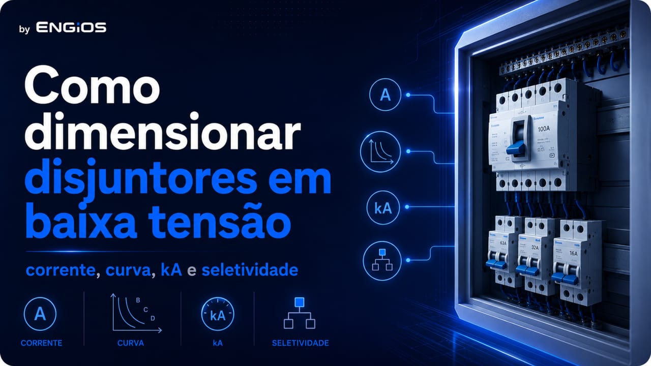
Understand how to size low-voltage circuit breakers considering design current, cables, trip curve, breaking capacity, prospective short-circuit current and selectivity.
Check it out!
Sizing a low-voltage circuit breaker means selecting a protective device compatible with the load, conductors, prospective short-circuit current, trip curve or trip unit, breaking capacity and installation coordination.
The direct answer is: a circuit breaker should not be sized only by the load current in amperes. Rated current is only one criterion. Proper sizing must verify that the breaker protects cables against overload, operates correctly under short-circuit conditions, withstands the available fault current at the installation point, avoids nuisance operation during normal starting and remains coordinated with other protective devices.
In building, commercial and industrial installations, this analysis involves NBR 5410, circuit-breaker product standards, panel documentation, the single-line diagram, conductor capacity, installation method, design current, RCDs, SPDs, selectivity, molded-case circuit breakers, motor circuit breakers and actual operating conditions.
What does sizing a circuit breaker mean?
Sizing a circuit breaker means selecting its electrical and construction characteristics so they are compatible with the protected circuit. This includes rated current, number of poles, trip curve or trip unit, breaking capacity, operating voltage, breaker type and function within the installation.
In practice, the circuit breaker must protect the circuit against overcurrents. These overcurrents may be overloads, when current remains above the permissible value for a certain time, or short circuits, when current rises rapidly because of a fault.
NBR 5410 treats overcurrent protection as a function that must interrupt abnormal conditions before thermal and mechanical effects damage conductors, connections, terminations and insulation.
Why is selecting by amperage alone not enough?
Selecting a circuit breaker only by amperage is a common mistake. The breaker amperage must be coordinated with design current and conductor current-carrying capacity, but it does not by itself determine whether the device is suitable.
Two breakers with the same rated current may have different trip curves, different breaking capacities, different product standards, different applications and different behavior under overload or short circuit.
A 32 A breaker, for example, may be unsuitable if cable capacity does not support that current under actual installation conditions. It may also be unsuitable if its breaking capacity is lower than the panel’s prospective short-circuit current.
Circuit design current
Design current is the current the circuit must carry in normal service considering the expected load. It depends on power, voltage, power factor, efficiency, utilization duty, simultaneity, demand and load type.
Design current should not be confused with breaker rated current. First, the load is defined and design current is calculated or determined. Then cables, installation method and a compatible protective device are selected.
In electrical design, design current is commonly represented by IB. It is one of the bases for coordinating conductors and protective devices.
Conductor current-carrying capacity
Conductor current-carrying capacity depends on cable cross-section, material, insulation, temperature, installation method, circuit grouping, number of loaded conductors and correction factors.
NBR 5410 uses Iz to represent conductor current-carrying capacity under the specified installation conditions. This means cable capacity is not only a property of nominal cross-section; it also depends on how the cable is installed.
A cable may carry one current in embedded conduit, another on a cable tray, another when grouped with several circuits and another at a different ambient temperature. Therefore, the circuit breaker should be selected only after the conductor’s actual installation conditions are assessed.
The IB ≤ In ≤ Iz criterion
One of the central NBR 5410 criteria for overload protection is the relationship among design current, protective-device rated current or setting and conductor current-carrying capacity.
In simplified form:
| Symbol | Meaning |
| IB | circuit design current |
| In | breaker rated current or current setting |
| Iz | conductor current-carrying capacity under installation conditions |
The logic is: circuit current must be less than or equal to the device rated current or setting, and that rated current or setting must be less than or equal to conductor capacity.
In practical terms: the breaker cannot simply be increased to stop tripping if the cable cannot carry the new current.
Sizing starts with coordination among load, cable and protection
Before choosing a curve, kA rating or manufacturer, the function of the circuit breaker within the installation must be understood. To review the conceptual basis, see Low-Voltage Circuit Breakers: types, function and specification criteria.
Conventional operating current
In addition to the relationship among IB, In and Iz, NBR 5410 also considers the device’s conventional operating current. For circuit breakers, this parameter relates to the point at which the device actually operates under overload within a time defined by the product standard.
This criterion is important because a circuit breaker does not operate instantaneously at every current above its rated value. Its operating characteristic depends on both overcurrent magnitude and time.
Therefore, circuit-breaker sizing involves not only the current marked on the device but also its trip curve and thermal and magnetic behavior.
Type B, Type C or Type D
Types B, C and D indicate magnetic operating ranges of modular circuit breakers. They help match the device to load behavior.
Loads with low starting current may require a different curve from motors, transformers, compressors or equipment with high transient current. If the curve is too sensitive, nuisance operation may occur. If it is too tolerant, operation may be difficult under certain short-circuit conditions, especially in long circuits.
NBR 5410 does not select the curve by commercial designation, but it requires the device to be compatible with overload protection, short-circuit protection, conductor capacity, prospective short-circuit current and energy withstand.
Load starting current
Some loads draw high current at startup. Motors, compressors, pumps, transformers and certain electronic equipment may generate transient peaks.
Protection must allow normal load starting while operating under abnormal conditions. This balance is part of sizing.
NBR 5410 recognizes that, in certain cases, peak load-current values must be considered to avoid unwanted operation. In practical terms, the designer cannot ignore actual load behavior.
Thermomagnetic circuit breaker, motor circuit breaker and molded-case circuit breaker
The circuit-breaker type also affects sizing.
Modular thermomagnetic circuit breakers are widely used in final circuits and distribution boards. Motor circuit breakers are intended for motor protection and normally provide thermal adjustment based on motor rated current. Molded-case circuit breakers are applied at higher currents, in feeders, main low-voltage switchboards and panels, and may provide broader settings and higher breaking capacities.
Choosing among these devices depends on circuit function, current, load, breaking capacity, need for adjustment and position in the electrical system.
The circuit-breaker type changes according to circuit application
DIN-rail breakers, motor circuit breakers and molded-case circuit breakers should not be treated as equivalent. To explore their application in panels and feeders, see Molded-Case Circuit Breaker: what it is, applications and specification criteria.
Breaking capacity in kA
Breaking capacity is the short-circuit current a circuit breaker can safely interrupt under the conditions declared by the manufacturer and product standard.
This value normally appears in kA, such as 6 kA, 10 kA, 25 kA, 36 kA or 50 kA. It is not the normal circuit current. It is a short-circuit criterion.
NBR 5410 establishes that device breaking capacity must be at least equal to the prospective short-circuit current at the installation point, except where suitable technical coordination with an upstream device exists.
Prospective short-circuit current
Prospective short-circuit current is the current that could flow if a short circuit occurred at a specific point of the installation. It depends on the source, transformer, cables, busbars, impedances and distance to the point being analyzed.
NBR 5410 requires prospective short-circuit currents to be determined at points considered necessary by calculation or measurement.
At a main low-voltage switchboard close to the transformer, short-circuit current may be high. At a distant final circuit, it may be lower. Therefore, the same circuit breaker may be suitable at one point and unsuitable at another.
Maximum and minimum short-circuit current
Maximum short-circuit current is used to verify whether the breaker has sufficient breaking capacity and whether conductors and devices can withstand the associated stresses.
Minimum short-circuit current is used to verify whether the device operates effectively at the farthest point of the protected line. In long circuits, short-circuit current at the end may be lower than at the origin.
NBR 5410 addresses this logic by requiring verification of circuit-breaker operation against minimum prospective current and of the energy let through by the device.
Icu and Ics
For circuit breakers complying with ABNT NBR IEC 60947-2, especially molded-case breakers and industrial devices, parameters such as Icu and Ics are used.
Icu is the ultimate short-circuit breaking capacity. Ics is the service short-circuit breaking capacity. In main switchboards, panels, feeders and main breakers, these values help assess circuit-breaker performance under short-circuit conditions.
These values must be read from the technical catalog at the applicable operating voltage. The same device can have different breaking capacities at different voltages.
Joule integral and let-through energy
The Joule integral, associated with I²t, indicates the thermal energy let through by the protective device before interruption. NBR 5410 relates this energy to conductor withstand.
In practice, it is not enough for the breaker to open. It must operate in a way compatible with the energy that cables and downstream devices can withstand.
This criterion is especially important in feeders, main switchboards, molded-case circuit breakers, coordination with upstream devices and applications with high prospective short-circuit current.
kA, Icu, Ics and let-through energy complete the short-circuit analysis
After defining current and trip curve, the design must compare the device with the prospective short-circuit current and conductor withstand. See Circuit-Breaker Breaking Capacity: what it is, Icu, Ics and prospective short-circuit current.
Selectivity between circuit breakers
Selectivity is coordination among protective devices connected in series so that, when a fault occurs, the device closest to the affected point operates preferentially.
In small installations, limited selectivity may be acceptable. In larger commercial, industrial and building installations, selectivity may be required to preserve continuity of service.
NBR 5410 addresses selectivity when safety or utilization reasons require service continuity to be affected only minimally. Circuit-breaker sizing should consider this objective where applicable.
Relationship with RCDs, RCCBs and RCBOs
RCDs, RCCBs and RCBOs perform functions associated with residual-current protection. They do not automatically replace overcurrent protection.
When an RCD is associated with or incorporated into an overcurrent protective device, the assembly must comply with the applicable criteria. When the RCD does not incorporate overcurrent protection, a suitable device must protect it against short-circuit stresses.
Therefore, circuit-breaker sizing must consider the presence of RCDs, RCBOs and RCCBs in the panel, especially in wet-area circuits, socket-outlets, specific loads and installations requiring additional protection.
Relationship with SPDs
An SPD protects against transient overvoltages but may require an associated overcurrent protective device according to the arrangement and manufacturer instructions.
When sizing the panel, the circuit breaker associated with the SPD must be compatible with the SPD, the prospective short-circuit current and the strategy for continuity of service or continuity of protection.
In main panels, coordination among SPDs, circuit breakers, RCDs and conductors should be treated as part of the protection system rather than as an isolated component choice.
How to size a circuit breaker step by step in design
A consistent technical sequence is:
1. identify the load and its function; 2. determine voltage, power and operating duty; 3. calculate or determine design current; 4. select the conductor installation method; 5. apply correction factors; 6. define conductor cross-section; 7. verify voltage drop; 8. select breaker rated current or setting; 9. verify the relationship among IB, In and Iz; 10. select the trip curve or trip unit; 11. consider load starting current; 12. calculate prospective short-circuit current; 13. verify breaking capacity; 14. assess let-through energy and conductor withstand; 15. verify selectivity and coordination; 16. coordinate RCDs, RCBOs and SPDs; 17. record the criteria in the design and single-line diagram.
This sequence prevents sizing from being reduced to a generic table lookup.
Common mistakes in circuit-breaker sizing
The most common mistakes are:
- selecting the breaker only by load power;
- selecting only by rated current;
- increasing breaker current to avoid operation;
- not checking conductor capacity;
- ignoring installation method and correction factors;
- not considering starting current;
- using Type C as a universal default;
- not calculating prospective short-circuit current;
- ignoring breaking capacity;
- confusing kA with circuit amperage;
- not checking selectivity;
- ignoring Icu and Ics in molded-case circuit breakers;
- not coordinating the breaker with RCDs, RCBOs or SPDs;
- replacing a device without updating the single-line diagram;
- not recording settings applied in the field.
These mistakes can cause nuisance operation, inadequate protection, conductor overheating, loss of continuity and documentation nonconformity.
How to document the circuit breaker in the electrical design
The electrical design should record the characteristics required for purchasing, assembly, inspection and maintenance.
The specification should indicate:
- circuit identification;
- design current;
- conductor cross-section;
- rated current or adjustment range;
- number of poles;
- trip curve or trip unit;
- operating voltage;
- breaking capacity;
- Icu and Ics, where applicable;
- prospective short-circuit current;
- device type;
- function in the panel;
- coordination with upstream and downstream devices;
- expected selectivity;
- association with RCDs, RCBOs or SPDs;
- setting, lockout and maintenance notes.
A specification such as “32 A circuit breaker” is insufficient. Even “250 A, 25 kA circuit breaker” may be incomplete if voltage, poles, trip unit, application and coordination criteria are not stated.
Sizing must become project documentation
Rated current, curve, breaking capacity, settings, selectivity and association with RCDs or SPDs should appear in the single-line diagram and design narrative. To connect this subject with technical documentation, see Low-Voltage Electrical Designs.
When should specialized engineering be engaged?
Specialized engineering is recommended when the installation includes main low-voltage switchboards, electrical panels, feeders, motors, molded-case circuit breakers, an on-site transformer, SPDs, RCDs, load expansion, recurring trips, panel overheating, lack of a single-line diagram or a need to comply with NBR 5410 and NR-10.
It is also recommended when the installation requires a short-circuit study, selectivity analysis, protection review, documentation of settings or technical standardization of panels.
Technical analysis makes it possible to turn circuit-breaker selection into a documented electrical-protection criterion.
Deepen your knowledge of the complete sizing method
This article presents the practical sizing sequence. For the complete methodology with standards criteria, decision matrix and technical checklist, see the white paper Method for Specification and Sizing of Circuit Breakers in Low-Voltage Electrical Installations. To explore grounding and equipotential bonding further, also see the eBook Electrical Grounding: Fundamentals, Design and Standardization.
Conclusion
Sizing low-voltage circuit breakers requires more than choosing a rated current. The breaker must be compatible with the load, conductors, trip curve, breaking capacity, prospective short-circuit current, let-through energy and system selectivity.
NBR 5410 provides the installation-level application basis. Product standards such as ABNT NBR NM 60898 and ABNT NBR IEC 60947-2 help define device characteristics for final circuits, boards, feeders and panels.
When sizing is properly documented, the circuit breaker stops being merely a panel item and becomes a verifiable part of the electrical protection system.
Technical references
[1] ABNT. NBR 5410:2004 — Low-voltage electrical installations.
[3] ABNT. NBR IEC 60947-1:2013 — Low-voltage switchgear and controlgear — Part 1: General rules.
[4] IEC. IEC 60947-2:2024 — Low-voltage switchgear and controlgear — Part 2: Circuit-breakers.
Frequently asked questions
Sizing should consider design current, conductor capacity, rated current or setting, trip curve, breaking capacity, prospective short-circuit current and selectivity.
No. Power helps estimate current, but it does not define the breaker by itself. Conductors, installation method, curve, short-circuit current and coordination must also be checked.
IB is design current, In is breaker rated current or setting, and Iz is conductor current-carrying capacity. The relationship expresses basic overload-protection coordination.
It depends on load behavior, starting current and available short-circuit current. Types B, C and D should not be selected by default without analysis.
Determine the prospective short-circuit current at the installation point and select a breaker with compatible breaking capacity.
It is the short-circuit current the breaker can safely interrupt under the conditions declared by the manufacturer and product standard.
Icu is the ultimate short-circuit breaking capacity, commonly used for breakers complying with ABNT NBR IEC 60947-2.
Ics is the service short-circuit breaking capacity, related to breaker performance under a short-circuit condition according to the product standard.
It may reduce trips, but it can leave conductors inadequately protected. Breaker current should not be increased without checking cables and the design.
No. Type C is common but not universal. Selection depends on the load, starting behavior, minimum short-circuit current and conductor protection.
A circuit breaker protects against overcurrents. Additional shock protection in many circuits involves residual-current devices according to the criteria of NBR 5410.
It may require an associated overcurrent protective device according to the SPD manufacturer, installation arrangement and prospective short-circuit current.
Motor rated current, starting current, starting method, duty and specific motor protection must be considered in addition to circuit criteria.
The protection basis is similar, but molded-case circuit breakers require greater attention to settings, Icu, Ics, selectivity, short-circuit current and panel application.
Rated current, curve or trip unit, breaking capacity, poles, voltage, protected circuit, coordination and the other criteria required for installation and maintenance should be documented.
Sizing should be performed by a qualified professional based on the electrical design, applicable standards, manufacturer data and actual installation characteristics.
Additional technical materials
Related solutions
- Low-Voltage Electrical Infrastructure
- Main Low-Voltage Switchboards and Low-Voltage Electrical Panels
- Electrical Safety and NR-10 Compliance
Related engineering services
- Low-Voltage Electrical Design
- Short-Circuit, Selectivity and Protection Coordination Study
- Electrical Installation Inspection
- Commissioning and Technical Acceptance
Related technical content
- Electrical Cable Sizing
- Cable Current-Carrying Capacity
- Breaking Capacity: Icu and Ics
- Circuit-Breaker Selectivity
- Molded-Case Circuit Breaker
