
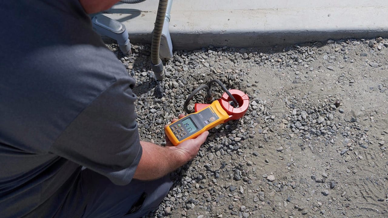
Understand grounding measurement, technical reports, ART, applicable standards, methods, and how NBR 5410 and NBR 5419 affect the assessment.
Check it out!
Grounding measurement is a technical activity intended to assess quantities and conditions associated with an installation’s grounding system. Depending on the objective, it may involve grounding resistance, electrical continuity, integrity of interconnections, and verification of conditions related to equipotential bonding.
The result of a measurement should not be interpreted in isolation. A value in ohms, by itself, does not characterize the overall quality of the grounding system, because the assessment also depends on the purpose of the system, the method used, soil characteristics, connections, conductor continuity, and integration with the electrical installation, the LPS, and protective devices.
Measurement may be used in inspections, diagnostics, maintenance checks, failure investigations, and the preparation of technical documentation. For the result to be traceable, the measured points, method, instrument, test conditions, values obtained, and technical interpretation must be recorded.
Therefore, measurement, report, technical assessment, and technical responsibility are related elements, but they are not equivalent. The contracted scope must clearly state whether the demand is only a field test or an engineering assessment with analysis, conclusion, and recommendations.
What is grounding measurement?
Grounding measurement is the process of assessing quantities associated with the grounding system. Depending on the technical objective, this assessment may involve grounding resistance, electrical continuity, connection integrity, equipotential bonding, interconnections with the LPS, its relationship with the low-voltage electrical system, and the operating conditions of surge protective devices.
Grounding is not an isolated element. It is part of a broader infrastructure connected to the protection of people, equipment, electrical systems, electronic systems, LPS, SPDs, electrical panels, racks, metallic structures, and conductive exposed parts.
To review the fundamentals before interpreting measurements, see the Electrical Grounding hub and the Electrical Grounding eBook.
Grounding resistance, soil resistivity, and continuity are different quantities
A significant portion of procurement errors arises from mixing different quantities. Grounding resistance characterizes the relationship between voltage and current associated with the grounding electrode or system relative to remote earth. Soil resistivity is a property of the medium and serves as input data for design and modeling. Electrical continuity verifies whether conductors and interconnections remain electrically connected. Step and touch voltage, in turn, addresses the potentials to which a person may be exposed at the ground surface.
| Quantity or verification | What it answers | Main reference | Typical application |
|---|---|---|---|
| Grounding resistance | Relationship between voltage and current of the electrode or system relative to remote earth | ABNT NBR 15749; NBR 5410 when prescribed | Technical reports and specific verifications |
| Soil resistivity/modeling | Electrical behavior of the soil with depth and across the area of interest | ABNT NBR 7117-1 | Grounding, LPS, and substation design |
| Electrical continuity | Integrity of conductors and interconnections | NBR 5410; NBR 5419-3:2026 | Commissioning, inspection, and maintenance |
| Step and touch voltage | Exposure of people to hazardous surface potentials | ABNT NBR 15749 and NBR 15751 | Substations and extensive systems |
| Fault-current path impedance | Condition for operation of the protective device | ABNT NBR 5410 | Automatic disconnection, especially in TN systems |
These verifications can complement one another, but they are not interchangeable. An earth tester does not replace a soil-resistivity survey; a resistance reading does not prove continuity of the entire grounding grid; and a continuity test alone does not demonstrate step-and-touch safety.
When is grounding measurement necessary?
Measurement may be required in different technical and documentary situations, such as issuing or updating a technical report, assessing grounding in low-voltage electrical installations, verifying grounding grids in substations and technical areas, diagnosing conditions after renovations and expansions, investigating failures, commissioning, audits, insurance requirements, and internal maintenance management.
In low-voltage installations, the need for and type of test depend on the grounding arrangement and the protective measure adopted. ABNT NBR 5410 differentiates, for example, the verifications applicable to TN, TT, and IT systems; therefore, generically procuring “a grounding measurement” may not answer the safety question that needs to be demonstrated.
In substations and larger grounding systems, the analysis may involve system resistance or impedance, ground-surface potentials, step and touch voltages, and the behavior of interconnected systems, according to the purpose of the study and the methods set out in ABNT NBR 15749 and ABNT NBR 15751.
For the LPS, an important distinction is required. ABNT NBR 5419-3:2026 establishes that grounding-resistance measurement is not required to verify the effectiveness of the LPS. Inspection focuses on compliance with the design and its governing standard, integrity of components, corrosion, electrical continuity of applicable elements, equipotential bonding, documentation, and the effects of additions or modifications to the structure. If the request is for an “LPS technical report,” the correct scope is broader than measuring resistance.
Measurements are also commonly requested in investigations of electrical surges, equipment damage, noise in electronic systems, technical handover of construction works, or commissioning. In these situations, grounding must be analyzed together with equipotential bonding, SPDs, continuity, diagrams, protection systems, and the installation’s history.
In all these cases, the test must result in traceable documentation: identification of the location and system assessed, objective, method, instrument, field conditions, measured points, results, limitations, technical interpretation, and professional responsibility.
Are grounding measurement, a grounding technical report, and ART the same thing?
No. These elements are related, but they are not equivalent.
Grounding measurement is the test or set of verifications performed in the field.
The measurement report records the data collected, the points assessed, the instruments used, and the results obtained.
The grounding technical report interprets these results and presents a technical conclusion on the condition assessed, including limitations, nonconformities, recommendations, and the need for corrective actions.
The ART records the technical responsibility of the qualified professional for the contracted service, under the rules applicable to professional practice in Brazil.
When procuring this type of service, the company should confirm whether it is contracting only a point measurement or a complete technical deliverable, with report, technical assessment, ART, photographic record, and recommendations for corrective actions.
Which standard applies to grounding measurement?
The applicable standard depends on the type of installation and the objective of the assessment.
For lightning protection systems, the ABNT NBR 5419:2026 series is the main reference for risk assessment, design, inspection, external LPS, surge-protection measures, and interfaces with electrical and electronic systems. Part 3 addresses protection against physical damage and hazards to life, including the LPS grounding system; Part 4 organizes protection measures for internal electrical and electronic systems.
For low-voltage electrical installations, ABNT NBR 5410 is the reference for safety requirements, protection, disconnection, equipotential bonding, and grounding in low-voltage electrical installations.
Other technical references may also apply depending on the type of installation, such as substations, industrial environments, classified areas, photovoltaic systems, data centers, hospitals, telecommunications, automation, and critical infrastructure.
Correct interpretation is not limited to checking whether the measured number is low or high. It is necessary to assess whether the system fulfills its intended function and whether grounding, equipotential bonding, surge protection, and the existing technical documentation are consistent with one another.
NBR 15749 and NBR 7117-1: measuring the system is not the same as measuring the soil
ABNT NBR 15749 is the specific reference for measuring grounding-system resistance and ground-surface potentials. It addresses methods, interference, safety, interconnected systems, energized installations, the fall-of-potential method, and high-current injection.
ABNT NBR 7117-1, on the other hand, addresses geoelectrical surveying and soil-resistivity modeling to support grounding designs. The standard shows that resistivity varies with soil composition, moisture, salinity, temperature, and layer structure. Therefore, using the resistance reading of an electrode as a substitute for geoelectrical characterization is technically incorrect.
When the need is to build or revise a grounding grid, an appropriate sequence may be survey → soil characterization/modeling → design → construction → inspection/testing → documentation. When the need is to diagnose an existing system, the sequence may begin with document and field inspection before defining which measurements are actually necessary.
Which methods can be used?
The choice of method depends on the type of installation, whether the system can be disconnected, interference from parallel conductors, the presence of interconnected grids, and the purpose of the test.
Methods commonly found in technical assessments include measurement with an earth tester, the fall-of-potential method, clamp-on earth testing where applicable, electrical-continuity testing, verification of equipotential bonding, and visual inspection of connections, inspection boxes, busbars, conductors, and interconnection points.
ABNT NBR 15749 is the Brazilian reference specifically addressing grounding-resistance measurement and ground-surface potentials. Among other topics, it establishes criteria for the fall-of-potential method, interference from buried metallic elements, stray currents, measurements in interconnected systems, and safety precautions during testing.
In the fall-of-potential method, it is not enough to position the auxiliary electrodes and record a single reading. The assessment must confirm that the current electrode is sufficiently far from the zone of influence of the system under test and that the resistance curve has a stable region. NBR 15749 provides, as a verification reference, a current-electrode distance of at least three times the largest dimension of the system and additional readings with displacement of the potential probe to confirm result stability.
A clamp-on earth tester can be useful when the electrical topology allows test current to circulate through closed paths, but its limitations must be assessed. In interconnected grids, energized installations, or systems with parallel paths, the instrument and method must be selected according to the actual configuration and purpose of the measurement.
The method should be selected by a qualified professional considering the actual installation conditions. In many cases, an isolated reading does not adequately represent the behavior of the grounding system.
When can a measurement be inconclusive or require another method?
The reliability of the result depends on the ability to create a test configuration compatible with the method. NBR 15749 warns of situations in which the conventional fall-of-potential method may become difficult or unsuitable, such as dense urban installations, large grounding systems, very low resistances, parallel paths, and limitations on the spacing of auxiliary electrodes.
Buried metallic elements, coupling between current and potential leads, stray currents, and overlap of zones of influence between the system under test and the auxiliary electrode can also introduce errors. In larger systems, the reactive component may become relevant, making impedance analysis more representative than a purely resistive interpretation.
When these limitations are relevant, NBR 15749 allows more robust approaches, such as high-current injection, which is especially useful for grounding systems in substations, power plants, and interconnected assemblies. The method also makes it possible to assess ground-surface potentials and the behavior of the system as a whole.
A result without context is not a diagnosis.
If the site does not allow the prescribed method to be applied, if there are multiple return paths, or if the system is extensive and interconnected, the technical report should record the limitations and justify the methodology used. A number without this traceability may not be sufficient for an engineering decision.
How does NBR 5410 change measurement in TN, TT, and IT systems?
At low voltage, the correct test depends on the grounding arrangement and the electric-shock protection mechanism. ABNT NBR 5410 does not treat every system as if a single resistance value in ohms were sufficient.
| System | Engineering verification | Why it matters |
|---|---|---|
| TN | Continuity of protective conductors and verification of fault-current path impedance associated with the characteristics of the protective device; under conditions provided for by the standard, calculations or measurement of protective-conductor resistance may be used | The objective is to demonstrate operation of automatic disconnection, not simply obtain an electrode resistance |
| TT | Measurement of exposed-conductive-part grounding resistance and inspection/testing of RCDs | Grounding resistance directly participates in verification of the protective measure |
| IT | Verification of first-fault current and double-fault conditions, by calculation or measurement according to the configuration | The diagnosis depends on how exposed conductive parts are grounded and on system behavior under fault conditions |
Before these tests, NBR 5410 provides for visual inspection and, where relevant, continuity testing of protective conductors and equipotential-bonding conductors. For new installations, extensions, and renovations, final verification should be documented and based on the installation as actually built.
This is an important procurement point: if the objective is to demonstrate the safety of an LV installation, the scope may need to include inspection of electrical installations, testing, and analysis of protective devices, not only grounding-resistance measurement.
What should a grounding measurement report or technical assessment contain?
A technical grounding-measurement document should provide sufficient information to enable traceability, analysis, and decision-making. In general, it is advisable to include identification of the client and assessed facility, measurement objective, technical scope of the service, standards and references adopted, inspection date, general site conditions, identification of measured points, measurement method used, instrument identification, results table, photographic record, technical analysis of the results, identified nonconformities, corrective recommendations, technical conclusion, identification of the responsible professional, and the ART associated with the service when contracted.
This set of information is important because grounding measurement is often used as documentary evidence in inspections, audits, and technical-regularization processes.
Why can an isolated value be misleading?
A common mistake is to assess the grounding system only by the value measured in ohms. Although grounding resistance is relevant information, it does not by itself explain the quality of the installation.
A system may present an apparently adequate value and still have continuity failures, compromised connections, lack of equipotential bonding, poorly coordinated SPDs, incomplete documentation, or incompatibility with the existing design.
The opposite can also occur: a measurement may indicate a high value at a given point, but the technical analysis must consider the method used, soil condition, existing interconnections, grid geometry, seasonality, system purpose, and test limitations.
Therefore, the technical documentation should interpret the results, not merely record numbers.
Relationship between grounding measurement, LPS, and SPDs
In LPS applications, grounding is part of the external subsystem and the structure’s equipotential bonding and should be analyzed together with the air-termination system, down conductors, interconnections, and internal protection measures. NBR 5419-3 and LPS grounding detail this function. SPDs, in turn, limit surges on electrical lines and, where applicable, on signal, telecommunications, CCTV, automation, and control lines.
Under ABNT NBR 5419-3:2026, inspection of LPS effectiveness does not depend on grounding-resistance measurement. The standard directs the inspection to verify the integrity and electrical continuity of the electrode and applicable conductors, compliance with the design, corrosion, equipotential bonding, documentation, the condition of Class I SPDs, and modifications made to the structure. Therefore, a request for “LPS measurement” must be technically framed before execution.
If the objective is to assess the LPS as a system, the appropriate approach is an LPS Inspection or, when a formal conclusion on compliance and recommendations is required, an LPS Technical Report. Grounding measurement may exist as a specific test within another technical objective, but it does not replace this systemic assessment.
The technical analysis should consider integration among these elements. A grounding system without adequate equipotential bonding can compromise the effectiveness of protective measures. Likewise, SPDs installed without proper coordination with the grounding and electrical systems may perform below expectations.
In many situations, grounding measurement should be analyzed together with the LPS design, electrical diagrams, SPD documentation, the LPS technical report, and maintenance history.
From the request to the scope: what should be procured in each situation?
In practice, many companies approach engineering asking for a “grounding test,” “grounding report,” or “earth-tester measurement,” but the actual problem may require a different scope. The initial diagnosis should identify which decision must be made using the result.
| Company situation | What must be answered | Most appropriate technical scope |
|---|---|---|
| I need a traceable resistance value for a defined purpose | What is the measured value and what are the test limitations? | Grounding measurement with a measurement report or technical report according to the contract |
| I do not know whether the existing grounding is technically adequate | Are there integrity, continuity, equipotential bonding, documentation, or installation-interface problems? | Technical inspection + selected measurements + technical report and recommendations |
| I need to demonstrate the safety of an LV installation | Are the protective measures and the TN, TT, or IT arrangement correctly verified? | Electrical-installation inspection + applicable NBR 5410 tests |
| I need an LPS technical report | Is the LPS intact, documented, and consistent with the design, modifications, and NBR 5419? | LPS Technical Report or LPS Inspection; not only grounding resistance |
| I will install or expand a grounding grid | Which geometry, material, and configuration meet the soil conditions and system requirements? | Soil characterization where applicable + Grounding Design |
| I have a substation or extensive system | Do step voltage, touch voltage, potentials, and grid current remain safe? | Grounding study according to NBR 15751 + specific measurements according to NBR 15749 |
| I have equipment failures, noise, or frequent SPD operation | Is the problem grounding, equipotential bonding, surges, protection, or EMC? | Integrated diagnosis; isolated resistance measurement may be insufficient |
| The grid exists, but there is no drawing or history | What is actually installed and in what condition? | Survey, inspection, continuity testing, as-built documentation, and definition of the required measurements |
The best scope does not start with the instrument; it starts with the engineering decision.
Before defining the number of points or test method, it is necessary to know whether the measurement will support commissioning, diagnosis, LV compliance, LPS assessment, a substation, audit, corrective design, or failure investigation. This definition avoids procuring a test that produces a correct number but does not answer the problem.
How should grounding measurement be procured?
When procuring grounding measurement, the company should clearly define the deliverable it expects to receive. Some contracts include only execution of the measurement. Others include a technical report, formal technical assessment, ART, photographic record, standards analysis, and a recommendations plan.
For technically adequate procurement, it is advisable to request the scope of points to be measured, measurement objective, type of document to be issued, indication of ART issuance, planned measurement method, instruments used, need for a calibration certificate, photographic record, compliance analysis, corrective recommendations, and deadline for delivery of the documentation.
The contract should avoid generic descriptions such as “measure grounding” when the actual objective is to obtain technical evidence for an audit, insurance, inspection, commissioning, maintenance, regularization, or acceptance of construction works.
Conclusion
Grounding measurement is a relevant technical activity for electrical safety, LPS documentation, SPD assessment, building maintenance, and regularization of installations.
When properly specified, it produces decision-making evidence: a technical report, formal technical assessment, ART, photographic record, analysis of results, and corrective recommendations. When treated only as a field resistance reading, it can leave important gaps for audits, insurers, inspections, and technical management of the building.
Companies that need to demonstrate the condition of the grounding system should procure the service with a clear documentary scope, a qualified responsible professional, and technical interpretation of the results, especially when the system is related to LPS, electrical installations, SPDs, substations, data centers, industrial environments, or critical infrastructure.
Technical references
[1] ASSOCIAÇÃO BRASILEIRA DE NORMAS TÉCNICAS. ABNT NBR 15749 — Measurement of grounding resistance and ground-surface potentials in grounding systems. Consulte a versão vigente no Catálogo ABNT.
[2] ASSOCIAÇÃO BRASILEIRA DE NORMAS TÉCNICAS. ABNT NBR 5410 — Low-voltage electrical installations.
[3] ASSOCIAÇÃO BRASILEIRA DE NORMAS TÉCNICAS. Série ABNT NBR 5419:2026 — Lightning protection. Consulte as quatro partes e versões vigentes no Catálogo ABNT.
[4] INTERNATIONAL ELECTROTECHNICAL COMMISSION. IEC 61557-5:2019 — Equipment for testing, measuring or monitoring of protective measures — Part 5: Resistance to earth. Consulte a publicação oficial na IEC Webstore.
[5] CONSELHO FEDERAL DE ENGENHARIA E AGRONOMIA. Technical Responsibility Record — ART. Consulte a regulamentação aplicável no Confea.
[6] BRASIL. Ministério do Trabalho e Emprego. NR-10 — Safety in Electrical Installations and Services.
[7] ASSOCIAÇÃO BRASILEIRA DE NORMAS TÉCNICAS. ABNT NBR 7117-1 — Soil parameters for electrical grounding designs — Part 1: Resistivity measurement and geoelectrical modeling.
[8] ASSOCIAÇÃO BRASILEIRA DE NORMAS TÉCNICAS. ABNT NBR 15751 — Substation grounding systems — Requirements.
Frequently asked questions
No. Measurement is the field activity or test. The technical report interprets the results and presents a conclusion, recommendations, and technical responsibility.
The need for an ART depends on the contracted scope and the technical responsibility involved. When a technical report, opinion, or responsibility for technical analysis is issued, the ART should be included in the procurement.
There is no single answer valid for every case. The result must be interpreted according to the type of installation, system purpose, measurement method, local conditions, and applicable standards.
No. Under ABNT NBR 5419-3:2026, verification of LPS effectiveness does not require grounding-resistance measurement. The inspection or technical report evaluates the system broadly, including design, integrity, electrical continuity of applicable elements, corrosion, equipotential bonding, SPDs, and documentation.
The deliverable may include a measurement report, technical report, ART, photographic record, table of measured points, method used, instrument identification, and corrective recommendations.
Complementary technical materials
Related solutions
Related engineering services
- Grounding Technical Report and Measurement
- Grounding Design
- Electrical Installation Inspection
- LPS Inspection
- LPS Technical Report
Related technical content
- Electrical Grounding
- Grounding Grid
- Equipotential Bonding
- LPS Grounding and NBR 5419-3
- TN, TT, and IT Grounding Arrangements
- Substation Grounding System and NBR 15751
