Understand how NBR 17227 guides arc-flash incident-energy calculation and its relationship with short-circuit studies, protection, PPE, labeling, and risk mitigation.
Check it out!
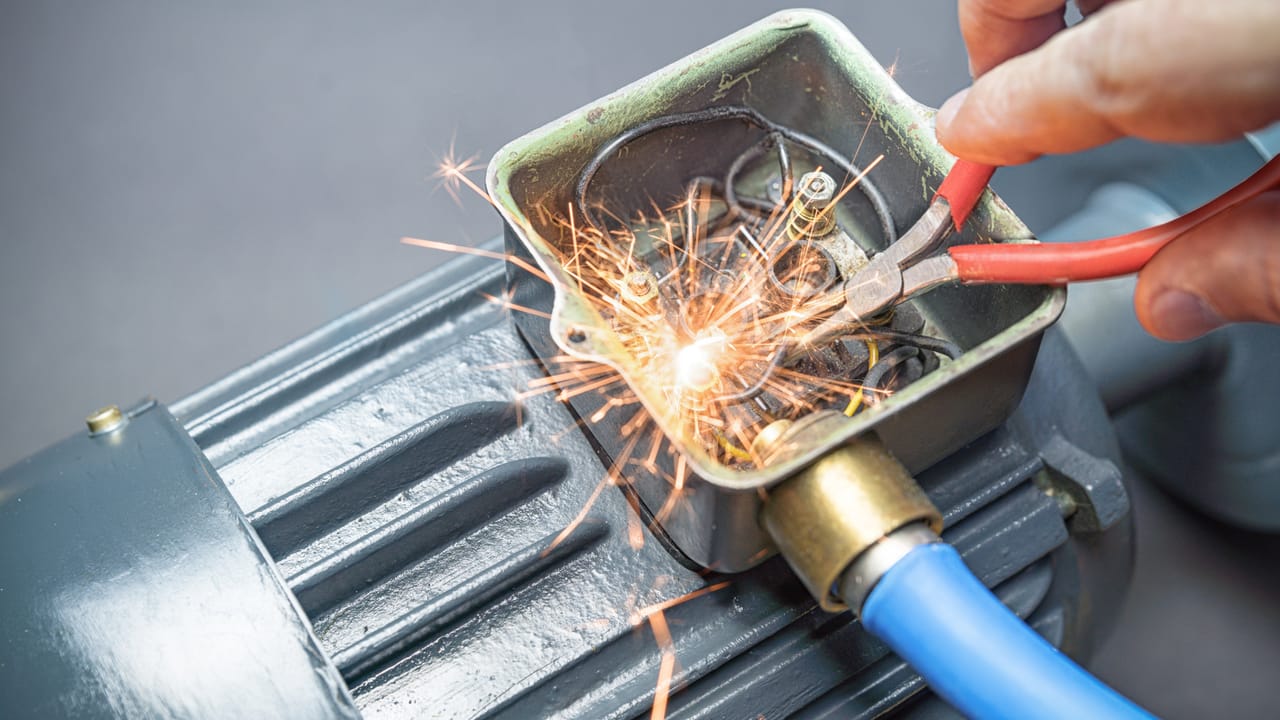
Arc flash is one of the most critical phenomena in electrical installations. In a few moments, the release of thermal energy can expose workers to severe heat, projected particles, intense light, noise, pressure, and significant operational consequences for the installation.
For this reason, arc-flash analysis cannot be treated merely as a PPE choice or a generic safety recommendation. It requires calculation, field data, electrical studies, risk analysis, labeling, procedures, and engineering measures.
This is the context in which $1 applies. The standard establishes a methodology for implementing arc-flash risk analysis, estimating incident energy, defining protection distances, selecting PPE, and adopting mitigation measures for workers and installations.
The central point is simple: incident-energy calculation transforms arc-flash risk into measurable information that can guide technical decisions about working distance, approach boundaries, labeling, protective clothing, protection settings, operation, maintenance, and installation documentation.
What is arc-flash incident energy
Incident energy is the amount of thermal energy received by a surface at a given distance from an arc-flash source. In electrical-safety terms, that surface practically represents the face and torso region of a worker exposed while performing an activity near energized equipment.
Incident energy is normally expressed in $1 or $1. The higher the calculated value, the greater the potential thermal severity of the event and the greater the need for protective measures.
It is important to distinguish incident energy from short-circuit current. Short-circuit current is an important variable, but by itself it does not represent the thermal risk of an arc. Incident energy also depends on arcing current, fault-clearing time, working distance, electrode configuration, enclosure type, system voltage, and operating mode.
Thus, two pieces of equipment with similar short-circuit currents can present very different incident-energy levels if protection operating times, working distances, or construction characteristics differ.
What NBR 17227 establishes
NBR 17227 provides a methodology for arc-flash risk analysis using calculations to estimate incident energy. Its objective is to support appropriate protection methods for workers and installations and to recommend actions to mitigate damage caused by incident energy during switching and maintenance activities.
The standard applies to installations with electrical equipment and conductors with rated voltages between $1. For voltages above 15 kV, it provides references used by the international technical community. The standard also addresses methods and parameters for calculating incident energy in DC systems up to $1.
The scope of NBR 17227 does not replace short-circuit and protection-coordination studies. On the contrary, the incident-energy study depends on them. If the installation does not have an updated short-circuit study, one should be prepared as the basis for the arc-flash study.
This distinction is fundamental. Incident-energy calculations should not be performed using outdated diagrams, assumed settings, or unverified data. They depend on an electrical model consistent with the actual installation.
Why the calculation depends on the short-circuit study
The short-circuit study provides the bolted-fault current, one of the essential variables for calculating arcing current. Arcing current, in turn, is used to estimate incident energy and the arc-flash boundary.
In practice, incident-energy calculations need to consider:
- utility supply sources;
- transformers;
- generators;
- motors;
- busbars;
- painéis e centros de controle de motors;
- circuit breakers, fuses, and relays;
- protection settings;
- plant operating modes;
- protection-device operating times;
- maintenance, contingency, and normal-operation scenarios.
This analysis is especially important in industrial facilities, data centers, power plants, substations, large corporate buildings, hospitals, ports, airports, and other critical environments with multiple sources, significant loads, and variable operating configurations.
There is no reliable incident-energy calculation without a reliable electrical basis.
Operating scenarios before the calculation
Before calculating incident energy, NBR 17227 directs the analysis to consider the electrical system’s operating scenarios. This includes actual supply configurations, the presence of generators, motor contribution, and more than one source connected to the same bus.
An installation may operate only from the utility, with the utility and generators in parallel, in islanded mode with internal generation, or under temporary maintenance configurations. Each scenario can change fault current, protection operating time, and the resulting incident energy.
For this reason, the worst incident-energy case is not always the normal operating mode. In some cases, a maintenance, contingency, or generator-operation configuration can produce a more critical condition.
Motor contribution must also be assessed. Induction and synchronous motors can contribute to short-circuit current for a period of time, affecting the energy integrated over the duration of the event.
In systems with generators, additional care is required because short-circuit current can vary over time. Under certain conditions, methods may be needed to represent current variation during the event rather than only a fixed value.
Incident-energy calculation steps
NBR 17227 organizes the analysis process into a technical sequence. This article does not replace calculations performed by a qualified professional, but the overall logic can be understood in steps.
The first step is $1. Single-line diagrams and data on transformers, generators, motors, switchboards, busbars, protective devices, settings, cables, phase spacing, enclosure dimensions, and actual working distances must be collected.
The second step is $1. The study must represent normal operating conditions and relevant alternative scenarios, including contingencies, parallel operation, maintenance, and operating restrictions.
The third step is $1, normally obtained from the short-circuit study. This current represents a fault condition with idealized impedance at the analyzed point.
The fourth step involves $1. Switchboards, cubicles, motor-control centers, and boxes can have different construction characteristics that affect thermal propagation of the arc.
The fifth step is $1. The model based on IEEE 1584 considers vertical, horizontal, open-air, or enclosed electrode configurations. This configuration influences arc behavior and incident-energy results.
The sixth step is $1. Arc-flash protection is typically based on incident energy at the worker’s face and torso while performing a task. Therefore, the actual or expected working distance must be considered carefully.
The seventh step is $1. This current is not equal to bolted-fault current because the arc has its own impedance. Calculated arcing current tends to be lower than bolted-fault current, but it can produce severe effects because of clearing time and released energy.
The eighth step is $1. This time depends on the operation of circuit breakers, fuses, relays, arc-flash relays, pressure devices, device communications, and any interlocking or zone-selective logic.
The ninth step is $1 for the assessed point. This calculation combines arcing current, clearing time, voltage, working distance, electrode configuration, enclosure, and other applicable parameters.
The tenth step is $1, representing the distance from the potential arc source at which incident energy reaches the reference value of 1.2 cal/cm².
Relationship between NBR 17227 and IEEE 1584
NBR 17227 uses $1 as a central reference for calculating incident energy in three-phase AC systems.
The model considers two main ranges: systems between $1 and systems above $1. It also establishes validation limits related to frequency, bolted-fault current, conductor spacing, working distance, enclosure dimensions, and electrode configuration.
Applying the method requires attention to model limits. When an installation, equipment item, or operating condition falls outside the validation parameters, the responsible engineer must assess the applicable methodology, limitations, and study assumptions.
Specialized software can support calculations, but it does not eliminate engineering responsibility. Results depend on input-data quality and technical interpretation of simulated scenarios.
Average arcing current and reduced arcing current
An important point in NBR 17227 is consideration of average arcing current and reduced arcing current, also called minimum arcing current.
This is because the worst incident-energy case does not always correspond to the highest current. In some situations, lower arcing current can cause the protective device to take longer to operate. The increased clearing time can result in higher incident energy.
Therefore, the study should compare the results and adopt the highest incident-energy value among the evaluated conditions. This prevents a simplistic conclusion based only on the highest short-circuit current.
Incident energy in direct-current systems
NBR 17227 presents methods, parameters, and references for evaluating incident energy in DC systems up to 1.5 kV. The scope of the standard, however, clarifies that the principal method presented for risk analysis does not apply directly to risk estimation in DC systems; therefore, this application requires careful use of the specific guidance and references provided for that configuration. This is relevant to battery banks, UPS systems, rectifiers, DC panels, industrial systems, energy storage, and some distributed-generation applications.
In direct current, arc extinction can be more critical because there is no natural current zero-crossing as in alternating current. This can make arc interruption more difficult and increase the importance of analyzing duration, arc resistance, conductor resistance, the source, and working distance.
For this reason, DC systems should not be underestimated. Even though the calculation approach differs, the risk-management principle remains: identify the hazard, estimate incident energy, establish controls, provide labeling, train personnel, and review the analysis when changes occur.
What should be included in the calculation report
The incident-energy calculation report should provide technical traceability. It must show how data were collected, which assumptions were adopted, which scenarios were simulated, and which results support labels, recommendations, and protective measures.
A technically consistent report should include, at minimum:
- installation identification;
- reference single-line diagrams;
- utility data;
- transformer, generator, and motor data;
- simulated operating modes;
- assessed equipment and points;
- bolted-fault current;
- calculated arcing current;
- arc-clearing time;
- adopted working distance;
- calculated incident energy;
- arc-flash boundary;
- recommended PPE;
- proposed mitigation measures;
- generated labels or signs;
- study assumptions and limitations;
- responsible engineer.
The report should be consistent with the installation’s document management, safety procedures, applicable electrical records, and risk assessments used to authorize activities on electrical installations.
Equipment labeling
NBR 17227 establishes that equipment with potential for arc flash must be labeled. This labeling is essential so workers and operating personnel understand the boundaries and requirements associated with the equipment.
The label or sign should indicate, at minimum:
- arc-flash danger and hazard warning;
- calculated incident energy in cal/cm²;
- considered working distance;
- safe approach boundary;
- equipment TAG;
- voltage level;
- specified PPE.
The information shown must correspond to the incident-energy study report or calculation memorandum and reflect the latest study performed. If protection is changed, switchboards are replaced, transformers change, load expands, or operating conditions change, labels may become obsolete.
Therefore, labeling equipment without a consistent report is a weak practice. The label is the visible face of an engineering study, not an isolated element.
Incident-energy calculation and PPE selection
PPE selection should result from the risk analysis and estimated incident energy. NBR 17227 treats PPE as one protective measure, but not as the first solution.
Before defining PPE, the analysis should consider elimination, substitution, engineering controls, administrative controls, work procedures, remote operation, maintenance, and reduction of protection operating time.
When residual risk still requires personal protection, clothing and other devices must be compatible with the calculated incident energy. Technical concepts include ATPV, EBT, and ELIM, related to the thermal performance of materials and clothing against arc-flash effects.
Compatibility among PPE items must also be evaluated. Face protection, balaclava or hood, gloves, helmet, hearing protection, footwear, and layered garments should form a coherent ensemble without compromising thermal performance or the mobility needed for the task.
PPE is an important barrier but should be treated as the last line of defense. Technical priority should be reducing risk at the source.
How to reduce incident energy
Incident-energy calculation is not only for quantifying risk. It also helps identify mitigation opportunities.
In new designs, measures may include optimization of instantaneous-trip settings, arc-detection relays using light, light and current, or pressure, ultra-fast devices, high-resistance grounding, arc-resistant switchgear, gas-insulated switchgear, circuit breakers and relays on transformer primaries, and implementation of zone-selective logic.
In existing installations, measures may include replacing fuses, creating maintenance-specific setting groups, modifying or replacing circuit breakers, limiting short-circuit current, splitting buses, upgrading protective devices, installing reclosers, remote operation, procedure review, and systematic equipment maintenance.
The logic is to reduce the probability of an arc, reduce event duration, increase working distance when technically possible, or control energy propagation.
This is an area where engineering has significant impact. A protection-setting change, selectivity change, arc-flash relay, remote operation, or switchboard upgrade can significantly reduce incident energy and improve installation safety.
Operation, maintenance, and study review
The incident-energy study should not be treated as a static document. It depends on the actual conditions of the electrical installation.
A review should be considered when there are changes to transformers, generators, switchboards, circuit breakers, fuses, relays, protection settings, loads, operating modes, diagrams, maintenance procedures, or supply configurations.
Maintenance is also part of risk management. Dust, corrosion, insulation failure, loose connections, cable damage, component aging, tools or metallic parts, and poorly maintained protective devices can increase the probability of faults.
In addition, an installation should be considered de-energized only after the appropriate procedures have been completed, including isolation, prevention of re-energization, verification of absence of voltage, temporary grounding, protection of adjacent energized parts, and lockout/tagout signage.
During de-energization and re-energization steps, arc-flash risk may still exist. Therefore, the analysis must be linked to the actual procedures performed by the team.
Common mistakes in incident-energy studies
A recurring mistake is calculating incident energy from outdated diagrams. If the single-line diagram does not represent the actual installation, the study result may be technically invalid.
Another mistake is considering only the normal operating scenario. The worst case may occur during maintenance, contingency, parallel sources, or operation with internal generation.
It is also common to select PPE before the calculation. This reverses the technical logic. PPE should be defined from incident energy, the task, and risk analysis.
Another problem is ignoring reduced arcing current. A lower current may delay protective-device operation and increase incident energy. Therefore, comparison among scenarios is essential.
Another error is treating the label as the end of the process. The label should be linked to the report, calculation memorandum, risk analysis, procedure, training, and periodic review.
How A3A Engenharia can support
A3A Engenharia works in design, diagnostics, and technical documentation for critical infrastructure, including electrical installations, system safety, engineering documentation, and solution integration.
For work focused on arc-flash risk and incident energy, technical activities may include field surveys, document updates, diagram organization, switchboard diagnostics, support for electrical modeling, assessment of critical points, mitigation recommendations, technical documentation, labeling, and an adaptation plan.
The objective is not merely to calculate an incident-energy value. It is to transform the study into applicable technical decisions: risk reduction, improved safety, document traceability, and support for operation and maintenance.
Conclusion
Incident-energy calculation is a fundamental step in arc-flash risk management. It connects electrical data, operating scenarios, protection, working distance, clearing time, labeling, PPE, maintenance, and engineering mitigation.
NBR 17227 consolidates an essential technical approach for installations requiring greater electrical-safety maturity. It shows that arc-flash protection should not be based on generic estimates, but on analysis, calculation, documentation, and continuous review.
More than a number on a label, incident energy should be understood as engineering information for decision-making. When properly applied, it helps reduce risk, guide procedures, specify appropriate protection, and improve the safety of workers and installations.
Need to assess arc-flash risk, review switchboards, or structure incident-energy studies in accordance with NBR 17227? Talk to A3A Engenharia’s technical team.
Technical references
[1] ASSOCIAÇÃO BRASILEIRA DE NORMAS TÉCNICAS. ABNT NBR 17227:2025 — Arco elétrico — Gerenciamento de risco de energia incidente, precauções e métodos de cálculo. Versão corrigida 3, 27 abr. 2026. Rio de Janeiro: ABNT, 2025.
[2] ASSOCIAÇÃO BRASILEIRA DE NORMAS TÉCNICAS. ABNT NBR 16384:2020: Segurança em eletricidade — Recomendações e orientações para trabalho seguro em serviços com eletricidade. Rio de Janeiro: ABNT, 2020.
[3] ASSOCIAÇÃO BRASILEIRA DE NORMAS TÉCNICAS. ABNT NBR 5410:2004: Instalações elétricas de baixa tensão. Rio de Janeiro: ABNT, 2004.
[4] ASSOCIAÇÃO BRASILEIRA DE NORMAS TÉCNICAS. ABNT NBR 14039: Instalações elétricas de média tensão de 1,0 kV a 36,2 kV. Rio de Janeiro: ABNT.
[5] ASSOCIAÇÃO BRASILEIRA DE NORMAS TÉCNICAS. ABNT NBR IEC 61439-1: Conjuntos de manobra e comando de baixa tensão — Parte 1: Regras gerais. Rio de Janeiro: ABNT.
[6] ASSOCIAÇÃO BRASILEIRA DE NORMAS TÉCNICAS. ABNT NBR IEC 61482-2: Trabalho sob tensão — Vestimenta de proteção contra perigos térmicos de um arco elétrico — Parte 2: Requisitos. Rio de Janeiro: ABNT.
[7] ASSOCIAÇÃO BRASILEIRA DE NORMAS TÉCNICAS. ABNT NBR IEC 62271-200: Conjunto de manobra e controle de alta-tensão — Parte 200: Conjunto de manobra e controle em alta-tensão em invólucro metálico para tensão acima de 1 kV até e inclusive 52 kV. Rio de Janeiro: ABNT.
[8] ASSOCIAÇÃO BRASILEIRA DE NORMAS TÉCNICAS. ABNT NBR IEC 62819: Trabalho sob tensão — Protetores oculares, faciais e de cabeça contra os efeitos do arco elétrico — Requisitos de desempenho e métodos de ensaio. Rio de Janeiro: ABNT.
[9] INSTITUTE OF ELECTRICAL AND ELECTRONICS ENGINEERS. IEEE Std 1584-2018 — IEEE Guide for Performing Arc-Flash Hazard Calculations. New York: IEEE, 2018.
[10] INSTITUTE OF ELECTRICAL AND ELECTRONICS ENGINEERS. IEEE Std 3002.3: Recommended Practice for Conducting Short-Circuit Studies and Analysis of Industrial and Commercial Power Systems. New York: IEEE.
[11] INTERNATIONAL ELECTROTECHNICAL COMMISSION. IEC 60909-0:2016 — Short-circuit currents in three-phase a.c. systems — Part 0: Calculation of currents. Geneva: IEC.
[12] NATIONAL FIRE PROTECTION ASSOCIATION. NFPA 70E: Standard for Electrical Safety in the Workplace. Quincy: NFPA.
Frequently asked questions
Incident energy is the amount of thermal energy received by a surface at a given distance from an arc-flash source. Under NBR 17227, it is normally expressed in cal/cm² or J/cm² and serves as a basis for assessing the thermal severity of the event.
Incident-energy calculation estimates workers’ thermal exposure in an arc-flash event and guides protective measures such as working distance, approach boundary, labeling, PPE selection, protection settings, and mitigation actions.
No. The incident-energy study depends on the short-circuit study. Bolted-fault current is one of the fundamental data points used to calculate arcing current, arc-clearing time, and incident energy.
NBR 17227 uses IEEE Std 1584:2018 as one of its main references for calculating incident energy in three-phase AC systems, considering parameters such as voltage, fault current, conductor spacing, electrode configuration, enclosure, and working distance.
Not necessarily. In some cases, a lower arcing current can increase protection operating time and result in higher incident energy. Therefore, the analysis must consider operating scenarios and reduced or minimum arcing current.
No. NBR 17227 applies to installations with equipment and conductors from 208 V to 15 kV in three-phase AC systems. It also addresses methods and parameters for calculating incident energy in DC systems up to 1.5 kV.
At minimum, the label should indicate an arc-flash hazard warning, calculated incident energy, considered working distance, safe approach boundary, equipment TAG, voltage level, and specified PPE.
This is not the recommended technical practice. PPE selection should be linked to risk analysis and estimated incident energy for the assessed point or task. PPE is a protective barrier, but it does not replace engineering, operation, and maintenance measures.
Incident energy can be reduced through measures such as optimizing protection settings, reducing operating time, using arc-flash relays, zone-selective logic, remote operation, interlocks, arc-resistant switchgear, upgrading protective devices, and reviewing operating procedures.
The study should be reviewed when relevant changes occur, such as transformer replacement, generator changes, protection-setting changes, switchboard modifications, load expansion, operating-configuration changes, diagram updates, or changes to maintenance procedures.
Complementary technical materials
Related solutions
- Electrical Safety and NR-10 Compliance
- Main LV Switchboards and Low-Voltage Panels
- Low-Voltage Electrical Infrastructure
- Medium-Voltage Electrical Installations
Related engineering services
- Incident-Energy and Arc-Flash Risk Study
- Short-Circuit, Selectivity, and Protection-Coordination Study
- Electrical Installation Inspection
- Electrical Installation Commissioning and Acceptance
- Low-Voltage Electrical Design
- Electrical Installations Record (PIE)
Related technical content
- Electrical Safety
- NR-10: electrical safety
- Electrical Installations Record (PIE)
- Protection Against Electric Shock
- Circuit-Breaker Selectivity
- Icw, Ipk, and Icc in Main LV Switchboards
- Electrical Single-Line Diagram
- Electrical Tests in Installations
