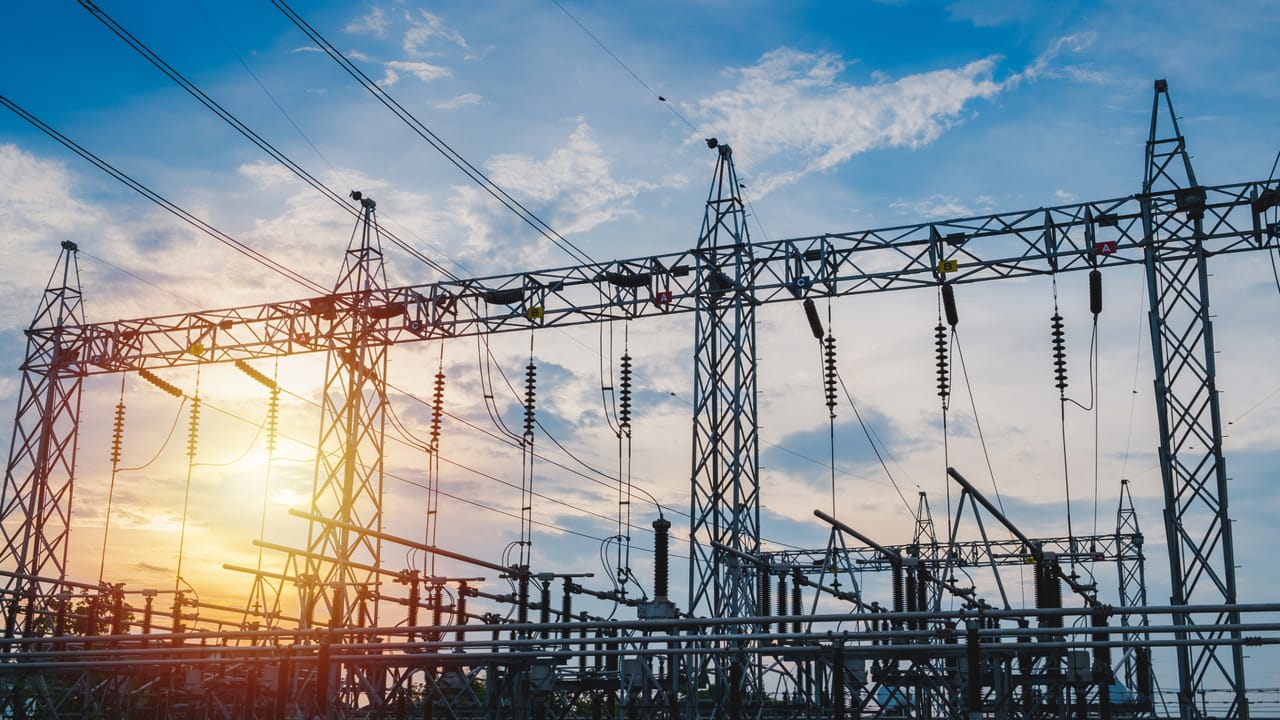
Understand what an electrical substation is, how it works, its types, components, bays, busbars, protection, grounding, automation, and auxiliary services.
Check it out!
An electrical substation is an installation that connects different parts of the power system and brings together equipment to transform voltage levels, sectionalize circuits, interrupt fault currents, measure electrical quantities, protect assets, and supervise operation.
It may be associated with generation, transmission, distribution, or the supply of industrial, commercial, and institutional consumers. Although size and technology vary, every substation must coordinate primary equipment, protection and control systems, grounding, auxiliary services, telecommunications, and physical infrastructure.
This article presents an integrated view of how a substation works, its main types, how components are organized into bays and busbars, and which interfaces must be considered in design, operation, maintenance, and modernization.
What Is an Electrical Substation
A substation is a connection and control point within the power system. Its function is not limited to stepping voltage up or down. Depending on the project, it may:
- connect a power plant to the transmission system;
- transform voltage between different system levels;
- distribute power to feeders or internal loads;
- interconnect lines and busbars;
- isolate equipment for maintenance;
- interrupt short-circuit currents;
- measure current, voltage, power, and energy;
- perform selective protection;
- allow local or remote control;
- record events, alarms, and oscillations;
- provide a grounding reference and control hazardous potentials.
Classifying an installation as a substation does not depend only on the presence of a transformer. The assembly must be analyzed according to the function performed, voltage level, electrical arrangement, switching devices, and operational responsibilities.
Substation, Primary Switchroom, and Transformer Station
In everyday use, the terms may appear interchangeable, but they represent different scopes.
A primary switchroom normally receives power at medium voltage and performs metering, protection, sectionalizing, and transformation to low voltage. It is common in industrial facilities, hospitals, shopping centers, and large buildings.
A transformer station tends to be a simpler installation intended mainly for local transformation and distribution. A substation, by contrast, may include multiple transformers, busbars, bays, lines, protection systems, automation, telecommunications, and different voltage levels.
The terminology adopted by the owner or utility does not replace the technical analysis of the arrangement and existing functions.
How an Electrical Substation Works
Operation can be understood by following the flow of energy and information.
Power enters through the supply line, cable, or busbar. Surge arresters limit overvoltages; disconnectors establish isolation conditions; current and voltage transformers provide signals for metering and protection; the circuit breaker performs switching and interrupts faults; the transformer changes the voltage level; and the busbar distributes power to other bays or feeders.
At the same time, relays and IEDs analyze currents, voltages, frequency, power, and equipment status. When they identify an abnormal condition, they trip the corresponding circuit breaker. SCADA systems record events, display alarms, and, where provided, enable remote operation.
Primary System
The primary system consists of equipment directly exposed to the voltage and current of the power circuit. It includes busbars, transformers, circuit breakers, disconnectors, CTs, VTs, surge arresters, cables, terminations, insulators, and earthing switches.
These components conduct, transform, sectionalize, interrupt, or measure electrical energy. Their specification considers voltage, rated current, short-circuit level, dielectric withstand, mechanical stresses, temperature, environment, and operating duty.
Secondary System
The secondary system brings together protection, control, supervision, automation, metering, telecommunications, and event recording. It includes relays, IEDs, controllers, RTUs, panels, industrial networks, servers, operator stations, and time-synchronization systems.
The secondary system determines how the installation detects faults, executes interlocks, displays states, records events, and communicates with operation centers.
Support Infrastructure
Operation also depends on AC and DC auxiliary services, battery banks, rectifiers, lighting, ventilation, drainage, foundations, cable trenches, access, oil containment, fire protection, fencing, and documentation.
A failure in these systems can make protection, control, or communication unavailable even when the main equipment remains electrically intact.
A substation must be designed as an integrated system, not as a collection of equipment.
Arrangement, protection, grounding, automation, civil infrastructure, and auxiliary services need to be coordinated from the project’s initial assumptions.
Main Types of Substation
Substations can be classified by their function in the power system, construction technology, voltage level, and operating regime. The same installation may belong to more than one category at the same time.
Step-Up Substation
A step-up substation increases the voltage produced by a power plant to reduce current and transmission losses. It is used in hydroelectric, thermal, wind, solar, and other generating facilities.
The arrangement must coordinate step-up transformers, generator connections, protection, synchronism, auxiliary services, and the interface with the transmission or distribution grid.
Step-Down Substation
A step-down substation reduces transmission or subtransmission voltage to distribution or utilization levels. It may supply urban networks, industrial facilities, commercial complexes, data centers, and critical infrastructure.
Transmission Substation
A transmission substation interconnects lines and transforms high- or extra-high-voltage levels. It normally includes multiple bays, busbars, complex protection systems, teleprotection, automation, telecommunications, and high availability requirements.
Application of ONS Grid Procedures requirements depends on the agent, the installation’s function, and its classification within the power system. These requirements should not be automatically generalized to every industrial substation or primary switchroom.
Distribution Substation
A distribution substation receives power at high or medium voltage and supplies distribution networks at lower levels. It may include power transformers, medium-voltage busbars, feeders, capacitor banks, reclosers, protection, and remote supervision.
Industrial or Customer Substation
An industrial substation supplies the internal loads of a plant, building, or complex. In addition to transformation, its design must consider process continuity, selectivity, on-site generation, motors, power quality, expansions, and operational safety.
AIS Substation
An AIS — Air Insulated Substation uses air as the main insulation medium. Equipment and busbars are installed in outdoor yards or sheltered environments with defined electrical clearances.
The solution generally requires more area but facilitates equipment visibility and may provide flexibility for expansion. The design must consider pollution, humidity, altitude, lightning, animals, corrosion, and maintenance.
GIS Substation
A GIS — Gas Insulated Substation uses enclosed modules with gas insulation. The technology reduces required area and protects energized parts from external contamination.
The solution requires specific engineering for interfaces, compartments, supervision, expansion, testing, and maintenance. Smaller area does not eliminate the need for access, safety, ventilation, and contingency planning.
Hybrid Substation
A hybrid substation combines compact modules with AIS equipment. It may be used for expansions, space constraints, or modernization projects in which part of the existing installation is retained.
Indoor Substation
An indoor substation uses switchgear, panels, or modules installed inside a building. It is common at medium voltage and in locations with area constraints, environmental exposure, or architectural requirements.
The design must coordinate compartmentation, internal arc, ventilation, escape routes, access, fire protection, pressure, cable trenches, cables, and auxiliary services.
Mobile Substation
Mobile substations are installed on trailers or platforms and may be used for contingencies, construction work, scheduled maintenance, or temporary service. Their connection requires assessment of grounding, protection, transportation, interfaces, stability, and safety of the temporary installation.
Conventional, Automated, and Digital Substation
A conventional substation uses hardwired secondary circuits and functions distributed across panels. An automated substation incorporates IEDs, communication networks, supervision, and remote commands. A digital substation further expands the use of standardized communications and digital data between field, protection, and control.
The term “digital” does not mean the total absence of conventional equipment. The architecture must be defined by implemented functions, interoperability, performance requirements, and integration testing.
Single-Line Diagram, Busbars, and Bays
The single-line diagram represents the electrical structure of the substation in simplified form. It shows lines, transformers, busbars, circuit breakers, disconnectors, CTs, VTs, surge arresters, and connections among circuits.
Protection zones, switching possibilities, maintenance conditions, transfer paths, and contingencies are defined from the single-line diagram.
What Is a Busbar?
A busbar is the common connection node between circuits at the same voltage level. It can interconnect lines, transformers, feeders, capacitor banks, reactors, and coupling bays.
Its design considers continuous current, short circuit, temperature rise, electrodynamic forces, insulation coordination, and future expansion.
Busbars may be rigid, flexible, enclosed in GIS, or installed inside medium-voltage switchgear.
What Is a Substation Bay?
A bay is the functional unit associated with a circuit. Each bay brings together the equipment required to connect a line, transformer, feeder, or other element to the busbar.
A bay may include a circuit breaker, disconnectors, earthing switch, CTs, VTs, surge arresters, relays, controls, metering, and automation interfaces.
Types of Bay
The main types are:
- line bay: connects a line to the substation;
- transformer bay: connects the transformer to the busbar;
- feeder bay: distributes power to a network or load;
- coupling bay: interconnects busbar sections;
- transfer bay: enables operation through a transfer bus or transfer breaker;
- capacitor-bank or reactor bay: connects reactive-compensation equipment.
Busbar Arrangements
Common arrangements include single bus, sectionalized single bus, main-and-transfer bus, double bus, ring bus, breaker-and-a-half, and double bus with double breaker.
The choice affects availability, flexibility, maintenance, protection complexity, area, and cost. The arrangement should be selected according to the consequences of circuit loss, operating regime, and expansion needs.
Main Substation Components
Components must be analyzed as part of an architecture. Specifying equipment in isolation does not ensure performance of the overall system.
Power Transformers
A transformer changes the voltage level between systems. Its main parameters include rating, winding voltages, impedance, vector group, insulation level, losses, cooling, short-circuit withstand, tap changing, and accessories.
Liquid-immersed transformers may have a conservator, radiators, Buchholz relay, pressure-relief devices, temperature indicators, and monitoring systems. Dry-type transformers have their own ventilation, insulation, temperature, and environmental requirements.
Circuit Breakers
A circuit breaker opens and closes circuits under load and interrupts short-circuit currents. It normally operates under commands from protection relays.
Its specification considers voltage, rated current, interrupting capacity, short-time current, operating sequence, opening time, arc-extinguishing medium, and operating mechanisms.
Vacuum circuit breakers are common at medium voltage. At higher voltage levels, gas-insulated circuit breakers or other technologies suitable for the application may be used.
Disconnectors
Disconnectors isolate sections, select busbars, establish bypasses, and create maintenance conditions. They do not replace the circuit breaker for interrupting short-circuit currents.
The design must coordinate switching capability, interlocks, position indication, actuation, supervision, and operating procedures.
Earthing Switches
Earthing switches connect isolated and de-energized sections to the grounding grid. They help discharge capacitances and reduce risks from induced voltages or inadvertent re-energization.
Operation must be interlocked with other equipment according to the installation philosophy.
Current Transformers
CTs reduce primary currents to values suitable for relays, meters, and supervision systems. They may be intended for protection, metering, or combined use.
Ratio, class, burden, saturation, accuracy limit factor, and thermal withstand directly influence protection and metering.
Voltage Transformers
VTs provide voltage signals for metering, protection, synchronism, supervision, and billing. They may be inductive or capacitive depending on voltage level and application.
Surge Arresters
Surge arresters limit atmospheric or switching overvoltages. They are installed close to transformers, lines, busbars, and other sensitive equipment.
Protection depends on coordination among protection level, equipment withstand, connection distance, grounding, and discharge current.
Cables, Terminations, and Connectors
Power cables connect equipment and may replace sections of busbar or overhead line. Terminations, joints, shields, and connections are critical parts of the insulation chain.
The design considers current-carrying capacity, short circuit, voltage drop, insulation, shield grounding, stresses, routes, bend radius, and environmental conditions.
Insulators and Structures
Insulators support conductors and equipment while maintaining electrical separation. Structures and foundations must withstand weight, wind, short-circuit forces, vibration, and installation loads.
Protection, Control, and Automation
The protection system identifies abnormal conditions and isolates only the necessary part of the installation. The objective is to limit damage and preserve continuity in healthy sections.
Relays and IEDs
Relays and IEDs receive signals from CTs and VTs, calculate electrical quantities, and perform functions such as overcurrent, differential, distance, breaker failure, overvoltage, undervoltage, frequency, and synchronism.
Settings must be coordinated with short-circuit studies, selectivity, topology, and equipment characteristics.
Interlocks
Electrical, mechanical, and logical interlocks prevent incompatible switching sequences. They can block closing an earthing switch onto an energized circuit, prevent operation of a disconnector under unsuitable conditions, or control transfers between sources.
Interlocking does not replace operating procedures, identification, and verification of the installation’s actual condition.
SCADA and Supervisory Systems
SCADA displays states, measurements, alarms, and events and may enable remote commands. The interface must distinguish valid, invalid, stale, and unavailable data.
Remote operation requires treatment of communication loss, command failure, position disagreement, and contingency conditions.
Telecommunications and Synchronization
Optical networks, switches, routers, gateways, radios, and synchronization systems connect IEDs, relays, servers, and operation centers.
Availability, latency, segregation, redundancy, management, cybersecurity, and time synchronization are essential requirements for event correlation and reliable operation.
Remote Assistance and Operational Monitoring
Remote assistance keeps the installation operationally supported from another location. It may combine supervision, telecontrol, video, communication with field teams, alarms, access control, and contingency procedures.
Video monitoring can support confirmation of equipment position or field conditions, but it is not automatically mandatory in every substation and does not replace signals, sensors, and interlocks.
Remote assistance requires integration among automation, video, telecommunications, and operating procedures.
The solution must be sized according to the operating regime, equipment criticality, and the evidence required for each switching operation.
Learn about the remote assistance and operational monitoring solution
Grounding System, LPS, and Surge Protection
The grounding grid conducts fault currents and controls potentials in the soil and structures. Its design considers resistivity, fault current, clearing time, step voltages, touch voltages, grid potential, and transferred potentials.
Structures, enclosures, fences, gates, neutrals, shields, surge arresters, panels, and metallic parts need to be equipotentially bonded according to the installation architecture.
Overall grounding resistance is only one parameter. A low value alone does not demonstrate that step and touch voltages are safe.
LPS and Surges
Exposed substations need to coordinate air terminals, down conductors, grounding, and protective clearances against lightning. Surge arresters on the primary system and SPDs in low-voltage, control, and telecommunications circuits limit conducted surges.
The design must also address electromagnetic compatibility, shielding, routing, and separation among power, control, and communication cables.
Auxiliary Services
Auxiliary services keep protection, control, communication, lighting, ventilation, and motors available.
Direct Current
The DC system normally includes a battery bank, chargers, distribution boards, and supervision. It supplies relays, trip and close coils, automation, telecommunications, and critical circuits.
Autonomy must be sized according to the functions that need to remain available during loss of AC supply.
Alternating Current
The auxiliary AC system supplies lighting, receptacles, panel heaters, ventilation, pumps, chargers, and building loads. It may be supplied by an auxiliary transformer, external grid, generator set, or redundant sources.
UPS Systems and Power Supplies
UPS systems and regulated power supplies may feed servers, operator stations, and electronic equipment. Their use must be coordinated with the DC system to avoid duplication without a clear function or single points of failure.
Physical and Civil Infrastructure
Civil infrastructure directly affects substation performance and maintenance.
Foundations and structures support equipment. Cable trenches and conduits organize cables. Drainage prevents flooding. Oil-containment basins control leaks. Firewalls and detection systems reduce fire consequences. Fences, gates, and access control restrict approach to energized areas.
The control building must accommodate panels, batteries, telecommunications, servers, and operator stations, with suitable HVAC, lighting, internal grounding, security, and access.
Clearances, Access, and Maintenance
The physical layout must respect electrical clearances, circulation, escape routes, equipment removal, vehicle access, platforms, and work areas.
An installation may comply with the electrical diagram and still be difficult or unsafe to maintain if there is no room for circuit-breaker withdrawal, transformer replacement, testing, or installation of temporary grounding.
Design, Studies, and Documentation
Substation design integrates electrical, civil, mechanical, automation, telecommunications, security, and fire-protection disciplines.
Documents and studies may include:
- single-line and three-line diagrams;
- load and demand studies;
- short-circuit and selectivity studies;
- equipment sizing;
- insulation coordination;
- physical layout and site plan;
- grounding design;
- cable and signal lists;
- functional and control diagrams;
- protection and control philosophy;
- automation and telecommunications architecture;
- technical specifications;
- testing and commissioning procedures;
- safety and operating documentation.
The scope varies according to voltage level, installation function, owner standards, and the utility or responsible agent.
Commissioning and Entry into Operation
Commissioning verifies whether equipment and systems were installed, configured, and integrated according to the design.
Tests may include insulation, transformation ratio, resistance, continuity, controls, interlocks, protection, trips, communication, alarms, synchronization, SCADA, auxiliary services, and end-to-end functional chains.
Energization should not be used as the first test of functions that could have been verified under controlled conditions.
Maintenance and Modernization
Maintenance should consider condition, criticality, history, technology, environment, and manufacturer recommendations. Cleaning and retightening are only part of the process.
Inspections, thermography, electrical tests, protection testing, grounding assessment, verification of auxiliary services, and documentation updates help identify degradation and discrepancies.
Modernization may involve relay replacement, circuit-breaker retrofit, new switchgear, automation, remote assistance, metering, arc protection, grounding upgrades, and review of auxiliary services.
Simplified Operating Example
Consider an industrial facility supplied at 13.8 kV with two transformers and a sectionalized low-voltage busbar.
The medium-voltage incoming supply includes sectionalizing, metering, protection, and a circuit breaker. The medium-voltage bus supplies two transformer bays. Each transformer reduces voltage to the utilization level. Low-voltage circuit breakers feed the main distribution boards, and the bus coupler allows loads to be transferred according to operating conditions.
CTs provide signals to the relays; the DC system maintains controls and trips; SCADA records states; and the grounding grid connects equipment and structures.
If a fault occurs on a feeder, the corresponding protection should open only the required circuit breaker. If a transformer is removed for maintenance, the arrangement and system capacity determine which loads can be transferred to the other source.
This example shows that operation depends on coordination among topology, capacity, protection, interlocks, grounding, and operations.
Common Errors When Analyzing or Designing a Substation
Common errors include:
- treating the substation only as a transformer;
- selecting equipment without a short-circuit study;
- ignoring selectivity and protection zones;
- choosing the arrangement only by lowest initial cost;
- failing to consider expansion and maintenance;
- sizing grounding only by resistance in ohms;
- failing to coordinate auxiliary services with critical functions;
- mixing automation and security networks without segregation;
- assuming every installation requires the same level of automation;
- applying transmission requirements to installations outside their scope;
- changing equipment without updating diagrams and settings;
- accepting the installation without end-to-end testing.
How to Select the Appropriate Architecture
The architecture should start from the installation’s function and the consequences of failure. Voltage level, power, load criticality, redundancy, availability, expansion, maintenance, area, environment, local or remote operation, and owner standards influence the solution.
There is no universally superior arrangement. A single bus may be suitable for a lower-criticality installation, while another operation may require a double bus, coupling, independent sources, or redundant bays.
The decision should be recorded using technical, operational, and economic criteria, not only by comparing equipment prices.
Conclusion
An electrical substation is an integrated system of power, protection, control, grounding, telecommunications, and infrastructure. Transformers, busbars, bays, circuit breakers, disconnectors, CTs, VTs, and surge arresters perform primary functions; relays, IEDs, and SCADA coordinate protection and operation; auxiliary services maintain control and communication; and the physical infrastructure enables safe installation and maintenance.
Understanding this integration is essential to design, operate, maintain, or modernize the installation. Reliability does not depend on a single piece of equipment, but on consistency among arrangement, specification, studies, documentation, procedures, and testing.
Technical References
[1] BRAZILIAN ASSOCIATION OF TECHNICAL STANDARDS. ABNT NBR 14039: medium-voltage electrical installations from 1.0 kV to 36.2 kV. Rio de Janeiro: ABNT.
[2] BRAZILIAN ASSOCIATION OF TECHNICAL STANDARDS. ABNT NBR 15751: substation grounding systems — requirements. Rio de Janeiro: ABNT.
[3] BRAZILIAN ASSOCIATION OF TECHNICAL STANDARDS. ABNT NBR IEC 61850-10: communication networks and systems for power-system automation — conformance testing. Rio de Janeiro: ABNT.
[4] BRAZILIAN NATIONAL SYSTEM OPERATOR. Grid Procedures: requirements applicable to installations and agents of the National Interconnected System. Rio de Janeiro: ONS.
[5] INTERNATIONAL ELECTROTECHNICAL COMMISSION. IEC 61936-1: power installations exceeding 1 kV AC and 1,5 kV DC — general rules. Geneva: IEC.
Frequently Asked Questions
It is an installation that connects parts of the power system and brings together equipment to transform voltage, sectionalize circuits, interrupt faults, measure electrical quantities, protect assets, and control operation.
They may be step-up, step-down, transmission, distribution, or industrial substations. By construction, they may be AIS, GIS, hybrid, indoor, or mobile. They may also be conventional, automated, or digital.
Transformers, busbars, bays, circuit breakers, disconnectors, earthing switches, CTs, VTs, surge arresters, relays, IEDs, auxiliary systems, grounding, telecommunications, and civil infrastructure.
A busbar is the common node connecting circuits at the same voltage level. A bay is the functional unit that connects a line, transformer, feeder, or other circuit to the busbar.
Not necessarily. Some substations perform only sectionalizing, switching, connection, or compensation without changing the voltage level.
To conduct fault and surge currents, control step and touch voltages, equipotentially bond structures, and reduce risks to people and equipment.
A conventional substation uses more hardwired secondary circuits and functions distributed across panels. A digital substation expands the use of communications and digital data among equipment, protection, and control according to the adopted architecture.
Equipment, insulation, controls, interlocks, protection, trips, measurements, communication, SCADA, auxiliary services, and the end-to-end chain of critical functions.
Additional Technical Materials
Solutions
- Medium-Voltage Electrical Installations
- Remote Assistance and Operational Monitoring in Substations
- Grounding and Equipotential Bonding
- Perimeter Protection
Engineering Services
- Medium-Voltage Substation and Primary Switchroom Design
- Short-Circuit, Selectivity, and Protection Coordination Study
- Commissioning and Technical Acceptance of Electrical Installations
- Grounding Design
- Grounding Technical Report
Additional Technical Materials
- Substation Arrangements and Topologies
- Substation Grounding System
- Disconnect-Switch Monitoring
- What Is SCADA in the Power Sector?
- Security in Power-System Automation Networks
