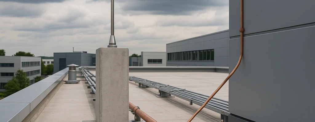
Review the critical points of NBR 5419:2026 for risk assessment, protection level, external and internal lightning protection, grounding, equipotential bonding, MPS, inspection, and documentation.
Check it out!
Application of NBR 5419:2026 requires a systems view. The most common error is to treat lightning protection as a set of isolated components — air terminals, down conductors, grounding, and SPDs — without connecting these decisions to risk assessment, protection level, the structure, internal systems, and documentation.
The critical points in a lightning-protection design appear precisely at the interfaces among the four parts of the standard. Part 1 establishes general principles; Part 2 addresses risk assessment; Part 3 defines requirements for the lightning protection system and protection against physical damage and life hazards; and Part 4 addresses protection measures for internal electrical and electronic systems.
The NBR 5419 Series Should Be Applied as an Integrated System
The 2026 edition technically updated all four parts of the series. A fragmented reading tends to produce incomplete designs because each part answers a different question.
| Part | Primary responsibility |
| NBR 5419-1:2026 | general principles, sources of damage, protection levels, and protection architecture |
| NBR 5419-2:2026 | risk assessment and damage frequency |
| NBR 5419-3:2026 | external and internal lightning protection system, inspection, grounding, and life hazards |
| NBR 5419-4:2026 | internal electrical and electronic systems and surge protection measures |
Complete lightning protection is broader than the external lightning protection system. It includes the lightning protection system, equipotential bonding, separation distance, and surge protection measures applicable to internal systems.
Risk Assessment Comes before Selecting Protection Measures
In the 2026 edition, Part 2 is titled Risk assessment. It establishes the procedure for determining when protection is required and which measures should be adopted.
The calculation considers components associated with different sources of damage, occurrence probabilities, and consequences. Risk should be compared with the applicable tolerable risk, and protection measures are selected to reduce the result to acceptable levels.
The 2026 edition also explicitly introduces analysis of damage frequency F, which is particularly relevant to the availability of systems and services. This broadens the engineering decision beyond immediate physical damage.
Sources S1–S4 and Damage Types D1–D3 Must Be Correctly Distinguished
NBR 5419-1:2026 organizes sources of damage according to lightning-strike location:
- S1: lightning strike to the structure;
- S2: lightning strike near the structure;
- S3: lightning strike to an electrical line or metallic service connected to the structure;
- S4: lightning strike near an electrical line or metallic service connected to the structure.
From these sources, the standard considers three basic types of damage:
- D1: injury to living beings due to electric shock;
- D2: physical damage such as fire, explosion, mechanical destruction, or release of hazardous substances;
- D3: failure of internal systems associated with LEMP.
Confusing source of damage, type of damage, and type of loss leads to errors in risk assessment and selection of protection measures.
The Protection Level Defines Design Parameters
The NBR 5419 series uses four protection levels, LPL I to LPL IV. Each level is associated with maximum and minimum lightning-current parameters.
These parameters affect decisions such as rolling-sphere radius, air-termination geometry, down-conductor spacing, component sizing, separation distance, and SPD and MPS requirements.
The protection level should not be chosen based on designer preference. It needs to result from risk assessment and project conditions.
External LPS, Internal LPS, and MPS Are Not the Same
The external lightning protection system consists of the air-termination, down-conductor, and grounding subsystems. Its functions are to intercept lightning, conduct the current safely, and disperse it into the earth.
The Internal lightning protection system has another function: preventing dangerous sparking inside the structure. This is achieved mainly through equipotential bonding or electrical isolation using separation distance.
The surge protection measures (MPS) address protection of electrical and electronic systems against overvoltages and LEMP effects and are developed mainly in NBR 5419-4.
Grounding Should Be Designed Based on Geometry and Integration
NBR 5419-3:2026 requires resistance to be considered and calculated in the design but emphasizes the importance of the geometry and dimensions of the grounding subsystem for behavior under impulse currents.
The standard considers a single integrated grounding infrastructure per structure preferable, common to power, signal, services, and lightning protection. Preferred arrangements include electrically continuous foundation reinforcement and a ring conductor. Vertical rods are treated as supplementary electrodes rather than a universal solution.
During inspection, electrode integrity is verified through electrical-continuity testing. Resistance measurement alone does not demonstrate lightning-protection-system compliance.
Air-Termination Design Must Result from a Method, Not Visual Distribution
The position of air-termination components should follow the methods provided by NBR 5419-3:2026 according to the protection level and structure geometry. Standards-based methods include the rolling sphere, protective angle, and mesh methods.
Simply distributing rods or conductors on a roof without geometric verification does not constitute a complete air-termination design. Structures with complex volumes, outdoor equipment, metallic roofs, photovoltaic systems, or projecting elements require specific coordination.
Separation Distance and Equipotential Bonding Are Design Issues
A lightning protection system can conduct current correctly to earth and still create dangerous sparking to nearby metallic elements or internal systems.
NBR 5419-3:2026 addresses this risk through two main strategies: electrical isolation by separation distance and equipotential bonding. This decision should be represented in the design.
SPDs Need to Be Part of a Coordinated Strategy
Installing SPDs in isolation does not constitute a complete MPS. NBR 5419-4 addresses a set of measures that may involve a coordinated SPD system, equipotential bonding, isolating interfaces, routing and segregation of lines, spatial or cable shielding, and lightning protection zones.
SPDs should be selected according to installation point, expected current, voltage protection level, and withstand capability of protected equipment. Coordination with the low-voltage electrical installation and overcurrent protective devices is also essential.
Lightning Protection Zones Structure Protection of Internal Systems
The LPZs represent volumes in which the electromagnetic environment associated with lightning is characterized. NBR 5419-1:2026 distinguishes LPZ 0A, LPZ 0B, and LPZ 1, 2, and higher, in which surge currents and fields can be progressively attenuated by protection measures.
The concept is especially relevant in installations with automation, telecommunications, instrumentation, data centers, and other sensitive electronic systems.
Inspection Must Verify Design, Physical Condition, and Continuity
Lightning-protection-system inspection should not be reduced to a grounding measurement. It should verify conformity with the design, physical condition of components, electrical continuity, connections, changes made to the structure, and maintenance of internal protection.
Changes in use, renovations, new rooftop equipment, photovoltaic systems, new piping, or façade changes can alter the protection scenario and require design review.
As-Built Documentation and Traceability Are Part of System Safety
A lightning protection system without reliable documentation becomes difficult to inspect and maintain. The documentation set should make it possible to identify risk-assessment criteria, protection level, air-termination system, down conductors, grounding, natural components, equipotential bonding, separation distances, SPDs/MPS, and inspection and test results.
In existing installations, the As-Built and as-built survey are essential to verify whether the actual condition still corresponds to the design and protection requirements.
The Critical Point Is Consistency across All Stages
The quality of a design according to NBR 5419 does not depend on an isolated component. It depends on consistency among risk assessment, protection level, air termination, down conductors, grounding, equipotential bonding, MPS, inspection, and documentation.
When these stages are treated as a single engineering system, risks can be reduced traceably and protection can be maintained throughout the installation lifecycle.
Technical References
[1] BRAZILIAN ASSOCIATION OF TECHNICAL STANDARDS. ABNT NBR 5419-1:2026 — Protection against lightning — Part 1: General principles.
[2] BRAZILIAN ASSOCIATION OF TECHNICAL STANDARDS. ABNT NBR 5419-2:2026 — Protection against lightning — Part 2: Risk assessment.
[3] BRAZILIAN ASSOCIATION OF TECHNICAL STANDARDS. ABNT NBR 5419-3:2026 — Protection against lightning — Part 3: Physical damage to structures and life hazard.
[4] BRAZILIAN ASSOCIATION OF TECHNICAL STANDARDS. ABNT NBR 5419-4:2026 — Protection against lightning — Part 4: Electrical and electronic systems within structures.
Frequently Asked Questions
Characterizing the structure and performing risk assessment are fundamental to determining the need for protection, risk components, and appropriate measures.
Not exactly. Complete protection includes the external and internal lightning protection system as well as measures to protect electrical and electronic systems against surges and LEMP.
No. In the 2026 edition, Part 2 is titled Risk assessment and also includes evaluation of damage frequency.
No. The design should consider geometry, resistivity, integration, and overvoltages; inspection should also verify continuity, physical condition, and conformity with the design.
Changes in use, renovations, structural modifications, new rooftop systems, new lines, or other changes that may affect protection can require technical reassessment.
