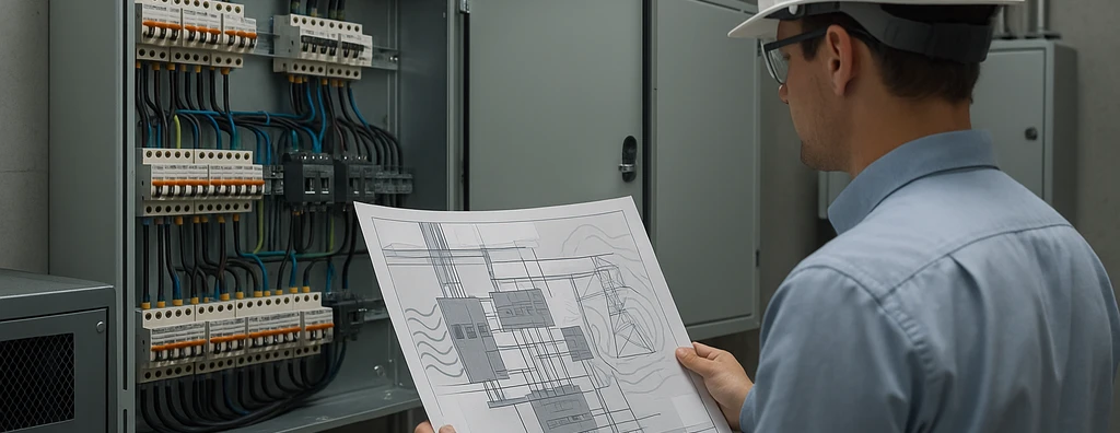
A technical workflow for locating and eliminating electromagnetic interference: symptoms, sources, coupling paths, measurements, shielding, filters, grounding, and SPDs.
Check it out!
Eliminating an electromagnetic interference (EMI) does not simply mean installing a filter, replacing a cable, or creating a new grounding point. The corrective action depends on identifying three elements: the disturbance source, the coupling path, and the affected equipment.
Without this diagnosis, an intervention may only temporarily reduce the symptom, transfer noise to another circuit, or create a new potential difference. For this reason, intermittent problems in automation, networks, video surveillance, instrumentation, and electronic equipment should be investigated through hypotheses and evidence.
This article presents a field workflow for locating causes and selecting mitigation measures without confusing trial and error with electromagnetic-compatibility engineering. When there is an actual failure to investigate, see the Electromagnetic Interference Diagnosis and Mitigation serviceFor the institutional and multidisciplinary approach, see the Electromagnetic Compatibility and Interference Control solution.
What Is Electromagnetic Interference?
EMI is a conducted or radiated disturbance that degrades the operation of a circuit, device, or system. It can cause:
- unexplained resets;
- communication loss;
- errors on industrial networks;
- noise or instability in sensors;
- degraded images in video systems;
- unintended commands;
- false alarms;
- data corruption;
- failures that occur only during starts or switching operations;
- recurring damage to electronic ports.
The electromagnetic compatibility (EMC) is the condition in which equipment operates in the same environment without producing or suffering incompatible disturbances. For the fundamentals of emissions, immunity, and coupling, see Electromagnetic Compatibility (EMC): What It Is, EMI, Causes, and Solutions.
Why Is the Failure Often Intermittent?
Many EMI sources do not operate continuously. Drives change frequency and load, motors start at specific times, contactors switch, generators transfer sources, and radios transmit intermittently.
Affected equipment may also respond differently depending on its state. An interface may fail only when transmitting, when the power supply is loaded, or when another metallic connection closes a current path.
The investigation needs to record the sequence of events. A reading taken after the failure may show the installation in a normal condition and fail to reveal the transient phenomenon that initiated the problem.
Step 1 — Define the Symptom Precisely
Descriptions such as “the network drops” or “there is a lot of noise” are insufficient. The diagnosis should answer:
- which equipment fails;
- which function is lost;
- how long it lasts;
- how the system recovers;
- which alarms or codes are recorded;
- which equipment was operating at that moment;
- at what times or operating regimes it occurs;
- which changes were made before the problem began.
The symptom needs a verifiable indicator. It may be an error rate, packet loss, incorrect sensor value, recorded reset, measured noise, or an event in a supervisory system.
Step 2 — Build a Common Timeline
Automation, network, UPS, relay, analyzer, generator, and security-system logs should use synchronized clocks. Temporal comparison makes it possible to determine whether the disturbance preceded the failure or appeared as a consequence of shutdown.
Relevant events include:
- motor starting or braking;
- frequency changes in drives;
- contactor switching;
- source transfer;
- transformer energization;
- operation of welding machines;
- radio transmission;
- storms and lightning;
- process or shift changes.
Correlation does not prove causation, but it guides the next tests.
Step 3 — Identify the Source, Path, and Victim
Disturbance Source
Common sources include drives, motors, switched-mode power supplies, UPS systems, transformers, busbars, welding, antennas, contactors, switching operations, and lightning.
A source can produce different phenomena simultaneously. A drive can generate power-supply harmonics, common-mode currents, radiated fields, and transients on motor cables.
Coupling Path
The disturbance can reach another device through:
- shared power supply;
- signal or communication conductors;
- shields;
- protective conductors;
- potential differences between grounding points;
- capacitive coupling;
- inductive coupling;
- radiated fields.
Affected Equipment
Vulnerability depends on equipment immunity, port function, installation, and received level. Two units in the same system may respond differently because they have different cables, power supplies, or references.
Step 4 — Separate Power-Supply Problems from Signal Problems
Voltage sags, interruptions, harmonics, imbalance, and power-supply transients can cause electronic failures. The Power Quality Analysis and Diagnosis helps verify this hypothesis.
However, a power supply within monitored limits does not eliminate other mechanisms. Common-mode noise, shield currents, radiated fields, and disturbances on communication lines may not appear on a conventional power-quality analyzer.
When the symptom occurs only on an interface, sensor, or camera, the investigation needs to include the signal and reference paths, not only the outlet powering the equipment.
Step 5 — Review Diagrams, Routes, and Connections
The survey should confirm the installed condition, including:
- sources supplying each device;
- power and signal routes;
- parallel run lengths;
- proximity to motors, panels, busbars, and the lightning protection system;
- crossings between infrastructure systems;
- continuity of cable trays and metallic conduits;
- shield terminations;
- rack and panel bonding;
- interconnections between buildings;
- equipotential bonding points;
- additional metallic interfaces.
Old diagrams may hide changes that created a new coupling path. A failure that began after renovation, expansion, or route changes should be analyzed starting from those modifications.
Step 6 — Choose Measurements Compatible with the Phenomenon
There is no single instrument for every interference problem. Selection depends on frequency, duration, and the suspected path.
Measurements may be required for:
- steady-state voltage and current;
- short-duration events;
- waveforms;
- frequency spectrum;
- common-mode current;
- current in shields and protective conductors;
- potential difference between references;
- communication signals;
- electric or magnetic fields;
- simultaneity between different points.
Bandwidth, sampling rate, sensors, connection method, and measurement category need to be appropriate. An instrument configured for aggregated RMS values may not capture fast transients.
Step 7 — Perform Controlled Tests
When safe and technically permitted, controlled tests help confirm hypotheses. Examples include:
- temporarily operating without a suspected load;
- changing the start sequence;
- supplying equipment from a suitable alternative source;
- temporarily replacing a metallic interconnection with fiber;
- temporarily changing a route;
- applying a compatible test filter;
- comparing behavior with and without a given interface.
The test should change one variable at a time. Changing cables, grounding, filters, and equipment simultaneously makes it impossible to determine which intervention produced the result.
Corrections Applied at the Source
Reducing the disturbance at its source is often more effective than protecting every victim individually.
Measures may include:
- reviewing drive installation;
- using reactors or filters specified for the application;
- reducing motor-cable lengths;
- correcting shield connections;
- adjusting switching frequency when technically permitted;
- installing appropriate suppression on coils and contacts;
- reviewing switching operations and load sequences;
- correcting loose or defective connections;
- separating the disturbance source from sensitive circuits.
The measure must respect manufacturer requirements and process performance. An unsuitable filter can saturate, overheat, or shift the problem to another frequency.
Corrections Applied to the Coupling Path
Segregation and Routing
Separating power and signal reduces coupling, but distance must consider current, frequency, parallel length, shielding, and infrastructure. There is no universal clearance in centimeters applicable to every installation.
Reducing loop areas, keeping outgoing and return conductors close together, and using crossings close to 90° are common measures.
Shielding
Shielded cables and enclosures can reduce fields and provide a controlled path for induced currents. Effectiveness depends on continuity, coverage, frequency, connectors, and terminations.
There is no universal rule requiring connection at one end or both ends. The decision depends on the application, frequency, potential differences, and manufacturer recommendations.
Isolation and Optical Fiber
Isolating interfaces and fiber can interrupt metallic paths. However, power supplies and other connections between devices need to be analyzed. Fiber does not correct a potential difference transferred through another route.
Equipotential Bonding
Racks, panels, cable trays, structures, and shields need to form a coherent equipotential-bonding network. Creating an independent “clean ground” can increase potential differences and force current through signal lines.
Corrections Applied to the Affected Equipment
When the source cannot be eliminated, it may be necessary to increase the immunity of the victim or its interface. Alternatives include:
- input filters;
- ferrites selected for the relevant frequency range;
- galvanic isolators;
- optical converters;
- power supplies with greater immunity;
- appropriate differential interfaces;
- shielded enclosures and penetrations;
- surge protection on power and signal;
- review of firmware and recovery parameters.
Replacing the equipment with another model may solve the symptom, but the report should record that the environmental cause may remain present.
When Should Filters and Ferrites Be Used?
Filters and ferrites are effective when applied to the correct frequency range and propagation mode.
A differential-mode filter may have little effect on a common-mode disturbance. An unsuitable ferrite may present low impedance at the relevant frequency. Normal current, voltage, saturation, and thermal conditions must also be considered.
The component should be installed close to the point to be protected and with connections that prevent recoupling between input and output.
When Should Grounding Be Reviewed?
Grounding needs to be reviewed when there are:
- potential differences between interconnected equipment;
- unwanted current in shields;
- long, high-impedance connections;
- racks or panels without equipotential bonding;
- discontinuous cable trays;
- independent grounding systems connected by signal cables;
- changes to the lightning protection system or electrical distribution.
Low-frequency electrode resistance alone does not describe behavior under fast transients. Geometry, length, and interconnections are essential.
When Should SPDs Be Installed?
SPDs are used to limit transient overvoltages and divert surge currents. They should be coordinated with operating voltage, equipment withstand capability, expected current, and location in the installation.
Protection should consider both power and signal. Equipment connected to two services may receive a surge through one port and discharge it through another.
The Surge Protection Measures solution integrates SPDs, equipotential bonding, shielding, routing, and protection zones according to ABNT NBR 5419-4:2026.
SPDs do not eliminate radiated fields, harmonics, or all high-frequency noise. Using them as a universal solution is technically incorrect.
Investigation Examples
Industrial Network Fails during Motor Starting
The hypothesis should consider voltage sag, contactor transient, magnetic field, drive common-mode current, parallel routing, and network reference. Measuring only average voltage may fail to capture the relevant event.
Camera Image Shows Periodic Interference
Power supply, communication link, grounding, PoE, routing near cyclic loads, and potential differences between endpoints should be analyzed. Replacing the camera without reviewing the infrastructure may transfer the failure to the new equipment.
Sensor Shows Unstable Readings near a Drive
The investigation should verify the cable, signal type, shielding, terminations, transmitter power supply, motor-cable route, switching frequency, and panel equipotential-bonding connection.
How Should the Correction Be Validated?
The correction should be verified using the same indicator that demonstrated the problem. If the failure was packet loss, validation needs to measure error rate and stability. If it was sensor noise, amplitude and behavior should be compared before and after.
Validation should cover the operating regimes in which the failure occurred, including starts, maximum load, transfers, and relevant environmental conditions.
An improvement observed for only a few minutes does not prove elimination of a problem that occurred weekly. The monitoring period should be compatible with the original recurrence.
What Should Be Included in the Diagnostic Report?
A technical report may include:
- description of the symptom;
- timeline of occurrences;
- surveyed diagrams and routes;
- sources and sensitive equipment;
- coupling mechanisms assessed;
- instruments and settings;
- measurements and tests performed;
- hypotheses confirmed or ruled out;
- diagnostic limitations;
- prioritized measures;
- verification criteria;
- results after intervention.
The document should distinguish installation diagnosis, functional testing, and laboratory product certification.
Errors that Make the Solution More Difficult
The most frequent errors include:
- replacing several components at the same time;
- installing filters without knowing the frequency and propagation mode;
- creating independent grounding systems;
- connecting shields through long conductors;
- assuming any shielded cable solves EMI;
- protecting only power and ignoring signal paths;
- measuring at only one point;
- attributing every electronic failure to power quality;
- concluding the cause solely from physical proximity to a source;
- failing to record the previous condition and the subsequent result.
Conclusion
Eliminating electromagnetic interference requires a method. The process begins by defining the symptom, building the timeline, identifying the source, path, and victim, and selecting measurements compatible with the phenomenon.
Corrective action can address the source, coupling path, or affected equipment. Segregation, shielding, equipotential bonding, filters, isolating interfaces, fiber, and SPDs are resources that need to be selected based on evidence.
Final validation is essential. Without comparing the same indicator before and after intervention, it is not possible to state that the cause was eliminated or that the system achieved adequate electromagnetic compatibility.
Technical References
[1] ABNT. NBR 5410:2004 — Low-voltage electrical installations.
[2] ABNT. NBR 5419-4:2026 — Protection against lightning — Electrical and electronic systems within the structure.
[3] ABNT. NBR IEC 61439-1:2016 — Low-voltage switchgear and controlgear assemblies.
Frequently Asked Questions
Define the symptom in measurable terms and build a timeline relating the failure to starts, switching operations, loads, and installation changes.
No. The filter needs to match the frequency, common or differential mode, current, voltage, and source/load impedances.
Not always. Independent grounding systems can create potential differences and force currents through signal lines. Equipotential bonding should be engineered.
Not automatically. Effectiveness depends on continuity, connectors, terminations, frequency, routing, and integration with equipotential bonding.
When it is necessary to interrupt a metallic propagation path or eliminate potential differences through the communication interface, while also analyzing the power supplies at both ends.
An SPD limits conducted surges. It does not eliminate harmonics, radiated fields, or all high-frequency noise.
By repeating the measurement or indicator that characterized the problem under the same operating regimes and for a period compatible with the original recurrence.
No. A field report assesses the installation and interfaces. Product certification depends on specific laboratory tests.
