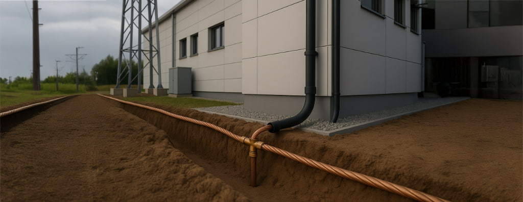
Learn how to design the grounding subsystem of a lightning protection system according to NBR 5419-3:2026: preferred arrangements, soil resistivity, ring electrodes, supplementary electrodes, equipotential bonding, continuity, and documentation.
Check it out!
The grounding design for a lightning protection system should be developed as an integrated part of lightning protection, considering electrode geometry, soil resistivity, current paths, equipotential bonding, step and touch voltages, material durability, and integration with the structure’s other installations.
ABNT NBR 5419-3:2026 makes it clear that grounding-subsystem performance cannot be reduced to a single resistance value measured in the field. The design should seek the lowest resistance reasonably compatible with the adopted arrangement, topology, and soil resistivity, but electrode integrity during inspection is verified primarily through electrical-continuity testing.
What Is the Function of Grounding in a Lightning Protection System?
In the external lightning protection system, the grounding subsystem receives current conducted by the air-termination and down-conductor subsystems and disperses it into the earth. Its function must be analyzed together with the other protection elements because inadequate geometry can increase overvoltages and dangerous potential differences even when the measured ohmic resistance appears low.
NBR 5419-3:2026 establishes that, for the high-frequency behavior associated with lightning, it is particularly important to study and improve the geometry and dimensions of the grounding subsystem.
This changes the design question. Instead of asking only “what resistance must I achieve?”, the analysis should consider:
- how current is distributed through the electrode;
- the soil resistivity and stratification;
- how the electrode integrates with the down conductors;
- which natural parts of the structure can be used;
- what surface voltages may arise;
- how equipotential bonding will be implemented;
- how the system will be inspected and maintained.
An Integrated Grounding Infrastructure Is Preferred
For lightning protection, NBR 5419-3:2026 considers a single integrated grounding infrastructure for each structure, shared by the existing installations: power, signal, services, and lightning protection.
This guideline is important because independent grounding systems can develop significant potential differences during a lightning event. Properly engineered integration reduces differential voltages and creates a more coherent equipotential reference for the structure.
Coordination should also consider NBR 5410 and, for protection of electrical and electronic systems against surges, the requirements of NBR 5419-4.
Preferred Grounding Arrangements
NBR 5419-3:2026 establishes a preferred order for the grounding subsystem.
Foundation Reinforcement with Horizontal Interconnection
The first option is to use the electrically continuous foundation reinforcement, with horizontal interconnection, for example through a grade beam or reinforced-concrete floor.
This arrangement uses a large contact area with the soil and can form an efficient natural electrode, provided electrical continuity is ensured according to standards criteria.
Foundation Reinforcement without Horizontal Interconnection
When the foundation has no horizontal interconnection at floor level, the standard allows the solution to be supplemented by an additional buried conductor. If such interconnection does not exist, potentially dangerous surface voltages should be assessed and preventive measures adopted.
Closed-Ring Conductor
When the natural electrode cannot be used, the arrangement using a closed-ring conductor around the structure is one of the reference solutions. The ring may include internal sections forming a mesh according to design needs.
The standard establishes that the ring electrode should be buried at a minimum depth of 0.5 m and, to mitigate dangerous surface voltages, positioned approximately 1 m around the external walls, considering the actual building conditions.
Rods Are Complementary, Not the Starting Point
A frequent mistake is to treat vertical rods as the standard solution for any lightning-protection grounding system. In NBR 5419-3:2026, rods are treated as supplementary electrodes and their application should consider soil conditions.
The need for supplementation depends on the existing arrangement, protection level, and the relationship between the average radius of the area covered by the electrode and the minimum length defined by the standard.
When the established conditions are not met, additional vertical or radial electrodes, or specific measures against step and touch voltages, may be required.
Therefore, “adding more rods” without analyzing geometry, resistivity, and current distribution does not constitute a complete grounding design.
Soil Resistivity and Electrode Length
Soil resistivity directly influences grounding-subsystem design. NBR 5419-3:2026 relates minimum electrode length to lightning-protection level and soil resistivity for certain classes.
This analysis should be performed during design, before deciding to add radial or vertical electrodes.
In heterogeneous soils, stratification can make an interpretation based only on a surface measurement inadequate. Therefore, the soil survey and arrangement selection should be consistent with the structure’s scale and criticality.
There Is No Single Resistance Value that Approves a Lightning Protection System
NBR 5419-3:2026 requires the electrode’s ohmic resistance to be considered and calculated during the design phase, with the objective of creating conditions that minimize dangerous overvoltages.
However, the standard does not establish a universal resistance value as a standalone acceptance criterion for every lightning protection system.
During inspection, when the objective is to verify electrode integrity, the indicated test is electrical continuity. This is particularly important because a system may show apparently low resistance and still contain discontinuities, deteriorated connections, or inadequate current paths.
Resistance measurement may form part of the engineering assessment, but it should not be treated as standalone proof of system compliance.
Materials and Dimensions Should Match Component Function
Another common error is to use minimum protective-conductor cross-sections from the electrical installation as if they were automatically valid for lightning-protection electrodes.
NBR 5419-3:2026 has specific tables for:
- air-termination and down conductors;
- non-natural grounding electrodes;
- equipotential-bonding conductors;
- materials and conditions of use.
For non-natural electrodes in direct contact with the soil, for example, the standard provides specific dimensions according to material and configuration. Copper cables used as non-driven electrodes are treated in a different cross-section range from ordinary protective conductors in electrical installations.
The specification should also consider corrosion, galvanic compatibility, mechanical stresses, and soil conditions. An unsuitable combination of materials can significantly reduce system service life.
Connections and Electrical Continuity
Grounding-subsystem connections are critical design points. They must withstand lightning-current stresses and maintain mechanical and electrical performance throughout service life.
The standard permits techniques such as electric welding, exothermic welding, and mechanical pressure or compression connections, subject to applicable conditions. Buried connections need to remain accessible in inspection boxes, except for the specified exceptions for certain permanent methods.
When foundation reinforcement is used as a natural component, its electrical continuity must be ensured and, in existing structures, verified according to the test procedures defined by the standard.
Integration with Equipotential Bonding and the Internal Lightning Protection System
Grounding should not be confused with the internal lightning protection system. NBR 5419-3:2026 defines the internal lightning protection system as the set of measures intended to prevent dangerous sparking inside the structure.
This is achieved primarily through:
- equipotential bonding; or
- electrical insulation by means of separation distance.
When power or signal lines cannot be connected directly to the equipotential bonding bar, the connection may be made indirectly through an appropriate SPD.
Detailed protection of internal systems against overvoltages and LEMP is addressed in NBR 5419-4.
Step and Touch Voltages
The design should verify situations in which lightning-current flow may create dangerous surface voltages. These conditions depend on electrode geometry, soil resistivity, down-conductor positions, and access by people or animals.
When necessary, NBR 5419-3 provides specific measures to reduce risks from step and touch voltages, which may involve improved equipotential bonding, access control, surface conditions, or modifications to the grounding arrangement itself.
This is another reason why electrode resistance alone does not represent overall system performance.
Stages of a Grounding Design for a Lightning Protection System
A consistent technical sequence involves:
1. characterize the structure and define the protection level resulting from risk assessment; 2. survey available natural components; 3. assess soil resistivity and conditions; 4. define the preferred grounding arrangement; 5. calculate and verify the need for supplementary electrodes; 6. specify materials, dimensions, and corrosion protection; 7. integrate with down conductors, equipotential bonding, power, and signal systems; 8. analyze step and touch voltages where applicable; 9. detail connections and test points; 10. document, inspect, and perform continuity tests.
Documentation and Handover
The design should traceably record the adopted criteria, subsystem drawings, materials, interconnection points, natural components used, calculation report, soil conditions, and inspection procedures.
In existing installations, the as-built survey and As-Built are particularly important. A design that does not correctly represent electrodes, interconnections, and natural components makes inspection difficult and can lead to decisions based on an incorrect field condition.
Lightning-protection grounding should be treated as engineering infrastructure integrated with the structure and electrical installations. Geometry, continuity, equipotential bonding, materials, and surface voltages are as relevant as any measured resistance value.
Technical References
[1] BRAZILIAN ASSOCIATION OF TECHNICAL STANDARDS. ABNT NBR 5419-3:2026 — Protection against lightning — Part 3: Physical damage to structures and life hazard.
[2] BRAZILIAN ASSOCIATION OF TECHNICAL STANDARDS. ABNT NBR 5419-1:2026 — Protection against lightning — Part 1: General principles.
[3] BRAZILIAN ASSOCIATION OF TECHNICAL STANDARDS. ABNT NBR 5410 — Low-voltage electrical installations.
Frequently Asked Questions
NBR 5419-3:2026 does not establish a universal resistance value as a standalone acceptance criterion. Resistance should be considered in the design together with geometry, topology, and soil resistivity.
Not by itself. To verify electrode integrity during inspection, NBR 5419-3:2026 indicates an electrical-continuity test. The complete assessment also considers the design, arrangement, connections, equipotential bonding, and physical condition.
Not as a universal solution. The standard treats rods as supplementary electrodes. The preferred arrangement may use electrically continuous foundations or a ring conductor, depending on the structure.
As a rule, NBR 5419-3:2026 considers a single integrated grounding infrastructure per structure preferable, serving power, signal, services, and lightning protection.
NBR 5419-3:2026 establishes a minimum depth of 0.5 m for the ring electrode and indicates an approximate position 1 m around the external walls to mitigate dangerous surface voltages.
