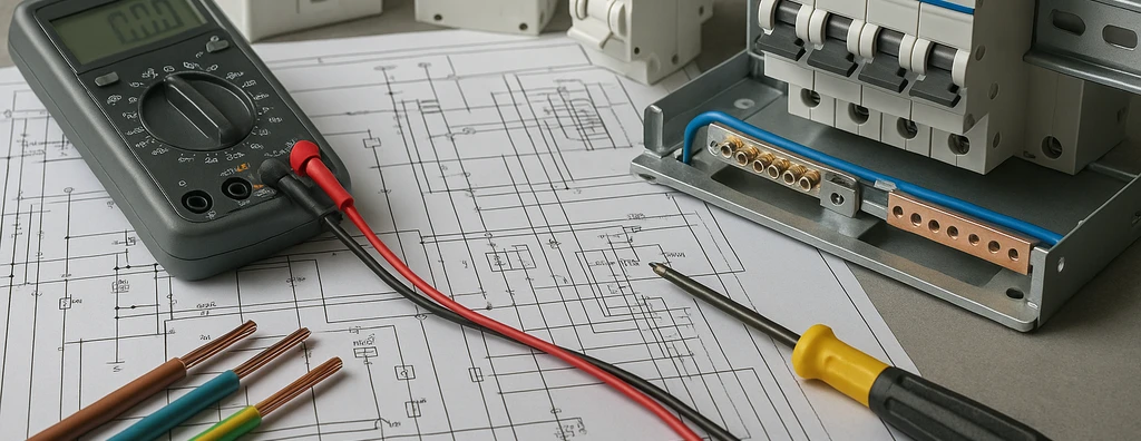
Learn the stages of a low-voltage electrical design: survey, loads, calculations, protection, switchboards, multidisciplinary coordination, documents, and acceptance.
Check it out!
A low-voltage electrical design transforms operational needs, loads, field conditions, and standards requirements into executable documentation. The process does not begin with drawing electrical points and does not end with issuing plans.
Survey, assumptions, calculations, coordination, specification, review, and acceptance criteria form a technical sequence. When one of these stages is omitted, important decisions end up being transferred to the construction site, the panel builder, or the maintenance team.
Definition of Objective and Scope
The first step is to understand why the design is being commissioned. Needs may include:
- new installation;
- renovation;
- load expansion;
- replacement of switchboards;
- equipment deployment;
- generator or UPS integration;
- standards compliance upgrade;
- documentation update;
- resolution of recurring failures.
The scope should identify areas, systems, boundaries, disciplines involved, deliverables, required surveys, and level of detail.
Design, inspection, and technical reports are not equivalent activities. When the existing condition is unknown, the work may need to begin with a survey and electrical-installation inspection.
Survey of Existing Documents and Conditions
Plans, diagrams, load schedules, design reports, lists, manuals, and previous records are analyzed. In existing installations, these documents should be checked against field conditions.
The survey may identify:
- unrecorded switchboards;
- modified circuits;
- added loads;
- replaced circuit breakers;
- unidentified cables;
- grounding different from the design;
- generators or UPS systems added later;
- absence of test records.
The objective is not merely to produce an inventory. It is to determine which information is reliable and which items need to be verified before calculations are performed.
Load Survey and Operating Regimes
Loads are classified by power, voltage, number of phases, duty, starting characteristics, power factor, electronic behavior, criticality, and expansion potential.
Installed power should not be confused with demand. Simultaneity, intermittency, seasonality, and operating modes affect transformers, feeders, switchboards, and alternative sources.
Essential loads, loads that cannot be interrupted, and loads that may be shed in an emergency should also be identified.
Definition of the Electrical Architecture
The architecture establishes how power will be distributed among the source, main low-voltage switchboard, secondary switchboards, final circuits, and loads.
The following are evaluated:
- radial or redundant topology;
- division by areas and systems;
- normal and emergency supply;
- generators and UPS systems;
- transfer switches;
- bypass;
- maintenance and expansion;
- selectivity between levels.
The architecture should limit the consequences of failures. A fault in one load should not shut down unrelated systems when separation is feasible.
Preparation of the Load Schedule
The load schedule organizes power, current, phases, circuits, protective devices, and conductors. It should remain consistent with plans, diagrams, and design reports.
In addition to nominal values, the document may record demand, spare capacity, identification, source, destination, installation method, and load-balancing criteria.
Spreadsheets without traceability between load, circuit, and switchboard make it difficult to verify sizing or update the design.
Conductor Sizing
Conductors are sized considering:
- design current;
- installation method;
- temperature;
- grouping;
- material and insulation;
- overload protection;
- short-circuit withstand capability;
- voltage drop;
- neutral and harmonics;
- protective conductor.
The largest conductor cross-section resulting from the applicable criteria should not be reduced without justification.
Infrastructure Sizing
Conduits, cable trays, ladder trays, raceways, shafts, and boxes need to be sized for fill, bending, pulling, heat dissipation, access, and expansion.
Infrastructure should be coordinated with architecture, structure, plumbing, HVAC, fire protection, telecommunications, and automation.
A route that proves unfeasible on site can change lengths, grouping, voltage drop, and thermal conditions. Therefore, coordination is not merely a drafting activity.
Selection of Protective Devices
Circuit breakers and fuses are selected according to current, trip curve or trip unit, interrupting capacity, category, selectivity, and coordination with conductors.
Selecting a circuit breaker based only on load current is not sufficient. The device must also interrupt the available short-circuit current and protect the circuit under actual installation conditions.
The article How to Size Low-Voltage Circuit Breakers examines the main criteria in greater depth.
Short-Circuit and Selectivity Study
In simple installations, part of the verification may be developed within the calculation report. In systems with multiple switchboards, transformers, generators, UPS systems, motors, or critical loads, a structured study is advisable.
The Short-Circuit, Selectivity, and Protection Coordination Study service evaluates operating modes, maximum and minimum currents, interrupting capacities, and trip curves.
Selectivity should not be assumed solely from the difference between device rated currents.
Protection against Electric Shock and Residual-Current Devices
The design defines the grounding arrangement, protective conductors, equipotential bonding, automatic disconnection, and application of RCDs where required.
Selection should consider sensitivity, type, rated current, selectivity, immunity, and expected leakage currents.
Electronic loads, filters, inverters, and power supplies may affect residual-current device behavior. The application needs to be compatible with the circuit.
Grounding and Equipotential Bonding
The design should represent busbars, protective conductors, equipotential-bonding connections, and interfaces with structures, piping, cable trays, racks, and external systems.
Indiscriminate separation among “electrical grounding,” “electronic grounding,” and the lightning protection system can create potential differences and unwanted paths through signal interfaces.
The Electrical Grounding solution can complement the design when a specific study, measurements, or upgrades to the existing installation are required.
SPDs and Surge Protection
SPD specification considers voltage, grounding arrangement, exposure, surge current, protection level, associated protection, coordination between levels, and connection length.
Where there is a lightning protection system, external lines, or sensitive electronic equipment, the design should integrate power and signals according to the surge protection measures architecture.
The Surge Protection Measures solution examines LPZs, equipotential bonding, shielding, routing, and coordinated SPDs in greater depth.
Specification of Main and Distribution Switchboards
Switchboards should not be represented merely by a rectangle in the diagram. The design needs to define currents, short-circuit ratings, devices, busbars, inputs and outputs, metering, spare capacity, access, environment, and verification requirements.
The Main and Low-Voltage Switchboards solution addresses specification, manufacturing, FAT, and acceptance according to ABNT NBR IEC 61439.
Integration of Generators, UPS Systems, and Alternative Sources
Alternative sources create distinct operating modes. The following should be analyzed:
- short-circuit current for each source;
- neutral reference;
- transfer;
- selectivity;
- bypass;
- backup autonomy;
- load restoration;
- maintenance.
The Critical Infrastructure Power solution is appropriate when continuity depends on integration among utility supply, generator, UPS, batteries, and redundant distribution.
Interface with Medium Voltage and Substations
When supply comes from a substation, the low-voltage design needs to consider transformers, medium-voltage protection, short-circuit current, grounding, the main low-voltage switchboard, and auxiliary services.
The Medium-Voltage Electrical Installations solution and the Substation Design service address this layer.
In remotely assisted substations, auxiliary supply, UPS, grounding, and SPDs also need to be coordinated with networks, cameras, and monitoring systems. The content on disconnect-switch monitoring illustrates this interface.
Interface with Telecommunications, Automation, and Electronic Security
The electrical design should provide circuits, switchboards, UPS, spaces, pathways, and equipotential-bonding references for telecommunications, automation, video surveillance, and access control.
The Telecommunications Design service defines the communications architecture, networks, links, equipment, and availability.
Discipline coordination should resolve responsibilities and prevent one discipline from assuming that another has defined power supply, infrastructure, or protection.
Multidisciplinary Coordination
Coordination verifies physical and functional interferences among electrical, architectural, structural, HVAC, plumbing, fire-protection, telecommunications, and automation disciplines.
It should resolve:
- switchboard spaces;
- access and maintenance;
- routes and penetrations;
- bases and supports;
- ventilation;
- loads;
- control interfaces;
- responsibility boundaries.
Preparation of Technical Documents
Main deliverables may include:
- electrical plans;
- single-line diagram;
- load schedules;
- calculation report;
- design report;
- technical specifications;
- bill of materials;
- construction details;
- inspection and acceptance criteria;
- procurement documentation.
Documents need to be consistent with one another. A change in the load schedule should be reflected in the diagram, calculations, plans, and lists.
Review and Quality Control
Before issue, the design should undergo technical review. Consistency, calculation traceability, compatibility among documents, references, identification, and interfaces should be verified.
The review should also assess constructability. A mathematically correct solution may be unfeasible if there is insufficient space, access, or installation condition.
Support for Procurement and Construction
The design may support bid normalization, equivalence analysis, technical responses, review of manufacturer documents, and clarifications during construction.
Field changes need to be assessed before execution. Substitutions driven by commercial availability should not reduce capacity, protection, or performance.
Inspection, Commissioning, and As-Built
Delivery should be verified through applicable inspections and tests. Continuity, insulation, polarity, identification, protection, controls, interlocks, and document correspondence are examples.
The Electrical Installations Commissioning and Technical Acceptance service structures evidence, punch-list items, and release.
The As-Built should record the final installed condition. It should not be produced merely by replacing the design title block without field verification.
Common Errors in the Design Process
Recurring problems include:
- starting drawings without defined assumptions;
- using installed load as demand;
- sizing cables without considering installation method and grouping;
- selecting circuit breakers without short-circuit calculations;
- specifying switchboards without assembly requirements;
- treating grounding and SPDs separately;
- omitting generator and UPS operating modes;
- failing to coordinate telecommunications and automation;
- issuing inconsistent documents;
- failing to define acceptance criteria.
From Design to the Installed System
The design is the technical basis for procurement, construction, inspection, and maintenance. Its quality depends on consistency among assumptions, calculations, drawings, specifications, and verifications.
The Low-Voltage Electrical Design service addresses the procurement of this activity. The Low-Voltage Electrical Installations solution organizes the broader journey, including diagnosis, studies, inspection, upgrades, and commissioning.
Technical References
[1] BRAZILIAN ASSOCIATION OF TECHNICAL STANDARDS. ABNT NBR 5410:2004 — Low-voltage electrical installations. Rio de Janeiro, 2004. Consult the current version in the ABNT Catalog.
[2] BRAZILIAN ASSOCIATION OF TECHNICAL STANDARDS. ABNT NBR IEC 61439-1 — Low-voltage switchgear and controlgear assemblies — Part 1: General rules. Consult the current version in the ABNT Catalog.
[3] BRAZILIAN ASSOCIATION OF TECHNICAL STANDARDS. ABNT NBR 5419-4:2026 — Protection against lightning — Part 4: Electrical and electronic systems within structures. Rio de Janeiro, 2026. Consult the current version in the ABNT Catalog.
Frequently Asked Questions
Definition of the objective and scope, followed by survey of documents, existing conditions, loads, operating regimes, and interfaces with other disciplines.
No. It should be coordinated with plans, diagrams, design reports, specifications, details, and inspection criteria.
The required depth depends on the installation. Systems with multiple distribution levels, transformers, generators, UPS systems, motors, or critical loads normally require structured assessment.
It should define the required power supply, spaces, pathways, UPS, grounding, and protection. Network and telecommunications architecture should be developed by the corresponding discipline.
To record the final installed condition, including approved changes, identification, diagrams, and data required for operation and maintenance.
Complementary Technical Materials
Related Solutions
- Low-Voltage Electrical Engineering
- Main and Low-Voltage Switchboards
- Electrical Safety and NR-10 Compliance
Related Engineering Services
- Low-Voltage Electrical Design
- Short-Circuit, Selectivity, and Coordination Study
- Electrical Installations Commissioning and Technical Acceptance
- Electrical Installations Inspection
- Detailed Technical Report on Electrical Installations
Related Technical Content
- NBR 5410
- Electrical Cable Sizing
- How to Size Low-Voltage Circuit Breakers
- Monitoring Disconnect Switches in Substations
