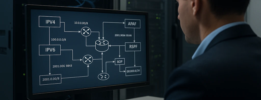
Understand how to structure IPv4/IPv6 addressing, subnets, route summarization, routing tables, OSPF, BGP, redundancy, and documentation in corporate and critical IP network designs.
Check it out!
Addressing and routing structures define how an IP network identifies its segments and selects the paths used by packets. A consistent design needs to coordinate the IPv4/IPv6 plan, prefixes, subnets, gateways, summarization, routing tables, dynamic protocols, redundancy, policies, observability, and documentation.
Addressing should not be treated as simple distribution of IP numbers, nor routing as a later device-configuration task. The two disciplines form a single architecture: the way address blocks are reserved affects summarization, convergence, segmentation, troubleshooting, multi-site expansion, and integration with the internet, cloud, OT, IP video surveillance, and other systems.
In corporate and mission-critical networks, the objective is to achieve a structure that is predictable, scalable, documentable, and verifiable, capable of growing without prefix overlap, maintaining coherent paths during failures, and allowing operations teams to understand why particular traffic follows a given path.
IP Addressing: Structure, Function, and Engineering Objectives
An IP address identifies an interface in an Internet Protocol architecture and allows hosts and routers to determine whether a destination is on the local network or whether the packet should be forwarded to a gateway. The effectiveness of the addressing plan directly affects subnet organization, summarization capability, and the clarity of routing policies.
IPv4
IPv4 uses 32-bit addresses, normally represented as four decimal octets, such as 192.168.10.25. The separation between the network portion and the host portion is determined by prefix length, for example /24.
The historical Class A, B, and C model helped shape IP-network terminology, but modern designs use CIDR — Classless Inter-Domain Routing. Therefore, the historical class of an address should not determine current network sizing.
The private blocks defined by RFC 1918 remain widely used in internal networks:
| Private IPv4 block | Aggregate prefix | Typical use |
| 10.0.0.0 to 10.255.255.255 | 10.0.0.0/8 | organizations requiring large internal address space |
| 172.16.0.0 to 172.31.255.255 | 172.16.0.0/12 | corporate networks and segmented environments |
| 192.168.0.0 to 192.168.255.255 | 192.168.0.0/16 | smaller networks and local segments |
Selection of the internal block should consider not only address quantity but also coexistence with VPNs, partners, acquisitions, temporary networks, cloud services, and possible future overlaps.
IPv6
IPv6 uses 128-bit addresses represented in hexadecimal and was developed primarily to expand address space and modernize IP operation. An address such as 2001:db8:10:20::1/64 may represent an interface on an IPv6 subnet.
IPv6 changes several design elements: autoconfiguration, Neighbor Discovery, routing, DNS, multicast, filtering, logging, and dual-stack operation. It should not automatically be considered more secure than IPv4. Security still depends on policies, hardening, access control, monitoring, and correct configuration.
In projects that still operate predominantly on IPv4, it is advisable to avoid decisions that would prevent future IPv6 adoption, especially in naming, IPAM, equipment, firewalls, monitoring, and operational processes.
Public, Private, and Special-Purpose Addresses
In addition to private blocks, the plan needs to distinguish public, loopback, link-local, multicast, documentation, and other reserved address spaces. This classification prevents special-purpose ranges from being misused as ordinary corporate networks.
Global authority over address spaces is coordinated by IANA, with regional distribution through the Regional Internet Registries. In private networks, the organization becomes responsible for its own internal governance.
CIDR, Prefixes, and Subnetting
CIDR replaced fixed-class logic with variable-length prefixes. A prefix /24, /27 or /30 expresses how many bits represent the network, allowing subnet size to be adapted to the actual requirement.
Detailed planning of masks, host counts, and block subdivision is discussed in greater depth in the article on IPv4 Subnetting and Subnet Sizing.
Subnets Should Be Created from a Hierarchy
Instead of creating the next available range at every expansion, the design should reserve blocks using stable criteria, for example:
- site or region;
- segment function;
- corporate, OT, or security environment;
- criticality;
- administrative domain;
- growth capacity;
- summarization requirements.
A multi-site structure may, for example, reserve an aggregate per site and subdivide it internally among users, servers, Wi-Fi, video surveillance, access control, voice, and management.
This hierarchy allows the address structure to carry operational meaning without depending on excessively rigid conventions.
Sizing Is Not Just Host Counting
A larger subnet provides more addresses, but it may also enlarge broadcast domains, increase the blast radius of errors, and complicate policies. A subnet that is too small may cause frequent renumbering and fragmentation of the addressing plan.
Sizing should consider current density, growth, Layer 2 behavior, mobility model, DHCP, asset type, and failure domain.
Route Summarization and Prefix Aggregation
Summarization reduces the number of prefixes that need to be propagated between parts of the network. Instead of advertising several subnets individually, a router can advertise an aggregate that represents them, provided the addressing plan was built contiguously and coherently.
Before redesigning prefixes and routes, it is necessary to understand the network’s actual state, dependencies, overlaps, paths, and limitations.
Technical Due Diligence structures this baseline and reduces the risk of renumbering or migration based on incomplete assumptions.
For example, four networks /24 consecutive networks may, depending on binary alignment, be represented by an aggregate prefix /22. This reduces table size and may limit propagation of internal changes.
Summarization provides engineering benefits:
- reduces route churn;
- reduces dependencies between domains;
- facilitates troubleshooting;
- improves policy readability;
- helps contain instability in internal topologies.
On the other hand, incorrect summarization can create black holes. If a router advertises an aggregate but does not have a valid path to every network covered by it, some traffic may be attracted and discarded.
| Situation | Expected effect | Risk |
| Contiguous and genuinely reachable prefixes | efficient summarization | low |
| Noncontiguous prefixes | inappropriate aggregate advertisement | black hole |
| Summary advertised at multiple points | greater resilience | unexpected paths if policy is inconsistent |
| No summarization in a very large network | greater granularity | more complex tables and convergence |
Routing Tables: RIB, FIB, and Path Selection
The routing table represents known prefixes and the available paths to reach them. Architecturally, it is useful to distinguish the Routing Information Base (RIB), where candidate routes are evaluated, from the Forwarding Information Base (FIB), which is actually used for forwarding according to the platform implementation.
A route entry typically includes:
- destination prefix;
- prefix length;
- next hop;
- outgoing interface;
- route source;
- protocol metric;
- preference or administrative distance when the platform uses that concept;
- additional attributes depending on the protocol.
Longest Prefix Match
When multiple routes cover the same destination, IP forwarding looks for the most specific prefix. This principle is known as longest prefix match.
Consider the routes:
| Prefix | Next hop | Interpretation |
| 0.0.0.0/0 | ISP | default route |
| 10.0.0.0/8 | internal core | corporate aggregate |
| 10.20.0.0/16 | Site B distribution | more specific route |
| 10.20.30.0/24 | application firewall | even more specific route |
A packet destined for 10.20.30.50 will follow the route /24because it is the most specific match, regardless of also being contained within the prefixes /16 and /8.
Metric Is Not the Same as Preference between Protocols
A metric is calculated within a routing protocol to compare paths learned by that protocol. Preference among routes from different sources may use another mechanism, such as administrative distance on certain platforms.
Mixing these concepts leads to incorrect diagnoses. A lower OSPF cost does not necessarily compete directly with a BGP route attribute or a static route in the same way on every platform.
Connected, Static, and Default Routes
Not every network requires a dynamic routing protocol.
Connected Routes
They arise from interfaces directly associated with a given prefix. They represent the device’s local connectivity.
Static Routes
They are configured explicitly and work well when the number of destinations is small, the path is predictable, or simple and deterministic control is required.
Static routes require governance. In larger topologies, they may accumulate hidden dependencies and make failures or changes more difficult to manage.
Default Route
The route 0.0.0.0/0 in IPv4, or ::/0 in IPv6, represents the path used when no more specific route exists. It is common at internet edges, remote sites, and access networks, but should be accompanied by coherent policies to avoid asymmetric paths or unintended exits.
Dynamic Routing Protocols
Dynamic protocols allow routers to exchange information and adjust the topology as links and paths change. The decision to adopt dynamic routing should consider scale, redundancy, convergence, operational capability, and policy requirements.
| Protocol | Category | Typical use | Core characteristic |
| RIP | IGP, distance vector | small and legacy networks | hop-count metric |
| OSPF | IGP, link-state | corporate and multi-site networks | topology view and SPF calculation |
| BGP | EGP/path vector | internet, multihoming, and inter-AS policies | attribute- and policy-based selection |
RIP
RIP has historical importance and may still exist in simple or legacy environments. Its hop limit and convergence model make it poorly suited to much of modern corporate architecture.
OSPF
OSPF is a link-state protocol used as an IGP in medium and large networks. It allows areas to be structured, paths to be calculated based on cost, and the scope of certain topology information to be limited.
The architecture of areas, LSAs, costs, and design criteria is detailed in the article OSPF: How It Works, Areas, LSAs, Costs, and Design Criteria.
BGP
BGP is used to exchange routes between autonomous systems and may also be used in specific internal architectures. Unlike an IGP, its strength lies in attribute-based policy control, allowing route selection and propagation to be influenced.
The role of ASN, peering, multihoming, filtering, and attributes is discussed in greater depth in the article BGP: ASN, Peering, and Design Criteria.
IGP and BGP Do Not Solve the Same Problem
A common mistake is to treat OSPF and BGP as equivalent alternatives. They operate in different domains.
In a typical architecture:
- an IGP distributes reachability and paths within the managed domain;
- BGP exchanges prefixes and applies policy between domains or defined edges;
- redistribution between protocols, when necessary, needs to be carefully controlled.
Uncontrolled redistribution can cause loops, loss of attributes, suboptimal routes, or unnecessary table growth. Whenever possible, protocol boundaries should be intentional and documented.
Addressing, VLANs, and Inter-VLAN Routing
VLANs separate Layer 2 domains. IP subnets organize Layer 3 communication. In many corporate LANs, there is an operational one-VLAN-per-subnet relationship, although the concepts belong to different layers.
Inter-VLAN routing may occur on Layer 3 switches, routers, or firewalls depending on where the organization wants to enforce policy and inspection.
The complete architecture should be analyzed as part of the Logical Network: VLANs, IP, Routing, and Segmentation, while isolation and control criteria between domains are discussed in greater depth in Network Segmentation.
| Decision | Addressing consequence | Routing consequence |
| create a video-surveillance VLAN | new prefix and gateway | policy for VMS and authorized services |
| separate management | dedicated administrative prefix | access restricted to management stations |
| divide users by site | blocks by location | possibility of summarization |
| separate OT from IT | distinct zones and prefixes | controlled boundary between domains |
Gateways and First-Hop Redundancy
End devices normally send traffic destined for other subnets to their default gateway. If that gateway exists on a single device, it can become a single point of failure.
First-hop redundancy protocols such as VRRP and equivalent vendor mechanisms can provide a virtual address associated with multiple devices. However, gateway redundancy alone does not solve uplink, power, routing, or shared-dependency failures.
A truly resilient architecture needs to analyze the complete path.
The presence of two devices should be validated through failover and convergence testing, not merely by physical inspection of the rack.
Convergence and Failure Domain
Convergence is the process by which routers reach a consistent view of the topology after a change. The effective recovery time perceived by the application depends on more than the routing protocol:
- failure detection;
- adjacency timers;
- new-path calculation;
- FIB update;
- gateway redundancy protocols;
- firewall state;
- application session;
- DNS and load balancers;
- WAN characteristics.
Therefore, specifying only “OSPF with fast convergence” is insufficient. The requirement should be translated into service behavior and validated through testing.
During implementation, routing changes can affect critical services even when individual devices are functioning.
Owner’s Engineering monitors design compliance, changes, evidence, and technical interfaces among contractors.
ECMP, Redundant Paths, and Load Balancing
Equal-Cost Multi-Path may allow multiple equal-cost paths for a given prefix, depending on platform and protocol support. This improves link utilization and resilience but does not mean that a single flow will necessarily be split across all paths.
Distribution normally depends on hashing using header attributes. Capacity planning should therefore consider aggregate flow distribution and not assume a linear sum of bandwidth for each individual session.
Asymmetric Routing
Asymmetric routing occurs when the forward path differs from the return path. IP itself can operate this way, but stateful devices, NAT, firewalls, and certain applications may require symmetry.
During troubleshooting, both directions need to be verified. Many incidents attributed to the firewall are actually caused by a missing return route or one that differs from the expected architecture.
Routing in Multi-Site, WAN, and Cloud Networks
In networks with multiple sites, the addressing plan should allow each site to have unique and, where possible, summarizable blocks. This facilitates integration through MPLS, SD-WAN, VPN, private links, or cloud connectivity.
A multi-site architecture needs to define:
- block reserved per site;
- local and shared prefixes;
- local or centralized default route;
- internet breakout;
- centralized services;
- WAN failover;
- cloud connectivity;
- behavior when the primary link fails;
- advertisement policy between regions.
Two links from different carriers do not guarantee redundancy if they share physical infrastructure, CPE, power, or a single routing policy that cannot converge correctly.
Addressing and Routing for Video Surveillance, Access Control, Voice, IoT, and OT
Specialized systems need to be considered in the logical plan from the beginning.
IP cameras may generate large volumes of traffic toward VMS and storage. IP voice is sensitive to delay, jitter, and loss. Access-control controllers depend on predictable communication with servers and integrations. OT and IoT may have specific update and security constraints.
The Network Traffic should be mapped before final path definition, especially where there are aggregation links, WAN connections, or firewalls in series.
Multicast Is Not Just “Another Type of Address”
Multicast allows a source to send traffic to a group of receivers. In networks using video, audio over IP, content distribution, or industrial applications, the design needs to distinguish host-membership mechanisms such as IGMP from protocols used to build multicast trees between routers, where applicable.
Treating multicast only as an address range can result in flooding, bandwidth consumption, or lack of reachability between domains.
Routing-Plan Security
Routing protection involves preventing false or unauthorized information from altering network paths.
Engineering measures may include:
- adjacency authentication where supported;
- prefix filters;
- redistribution control;
- restriction to authorized neighbors;
- control-plane protection;
- separation of the management network;
- logging and telemetry;
- change control;
- validation of BGP advertisements as appropriate to the context.
In IPv6, the presence of IPsec support in the protocol does not mean traffic is automatically encrypted. Effective use of encryption needs to be defined by the architecture and application.
Route and Flow Observability
Operating routing without observing state changes increases diagnostic time. The team needs to be able to identify adjacency changes, flaps, lost prefixes, next-hop changes, and unexpected table growth.
The Network Monitoring tracks availability, interfaces, and metrics. The NetFlow and Flow Analysis help determine who is using a given path. The FCAPS-Based Network Management organizes fault, configuration, performance, security, and accounting as an operational discipline.
| Evidence | Question answered |
| routing table | which prefixes are known? |
| adjacencies | which neighbors are active? |
| protocol logs | when did the change occur? |
| NetFlow/IPFIX | which flows used the path? |
| SNMP/telemetry | how did interfaces and resources behave? |
| traceroute/tests | which path was observed? |
IPAM and Source of Truth
As the network grows, isolated spreadsheets cease to be sufficient for controlling prefixes, gateways, reservations, VLANs, and dependencies. An IP Address Management process can centralize the plan and reduce conflicts.
The source of truth should record not only addresses but also the relationships among:
- sites;
- prefixes;
- VLANs;
- VRFs;
- gateways;
- interfaces;
- devices;
- DNS/DHCP services;
- owners;
- reservation and usage status.
The tool does not replace governance: addresses need to follow a change process, and changes implemented in production should be reflected in the As-Built.
Addressing and Routing Documentation
An executable design needs to translate the architecture into clear documents. The Network Diagram should show how domains and paths relate without trying to concentrate every detail in a single figure.
A documentation package may contain:
| Document | Minimum content |
| IP plan | prefixes, purpose, gateway, DHCP, and reservations |
| VLAN matrix | ID, name, prefix, site, and function |
| summarization table | aggregate prefixes and advertisement point |
| routing matrix | source, destination, protocol, and policy |
| logical diagram | sites, zones, L3 devices, and paths |
| adjacency table | expected neighbors and interfaces |
| redundancy plan | gateways, links, failover, and convergence |
| test plan | scenarios, criteria, and evidence |
| logical As-Built | actually implemented and accepted state |
How to Design Addressing and Routing in a Coordinated Manner
An engineering sequence reduces rework:
The IP plan, gateways, summarization, and protocols need to form a single documented architecture.
Logical Network Design transforms connectivity, segmentation, redundancy, and operational requirements into diagrams, matrices, standards, and acceptance criteria.
Learn About the Logical Network and Corporate Network Design Service
- survey sites, systems, users, assets, and flows;
- map constraints of the existing network;
- reserve blocks by domain and location;
- size subnets;
- define gateways and L2/L3 boundaries;
- establish the summarization policy;
- choose static routes or dynamic protocols;
- define redundancy and expected convergence;
- model failures and alternate paths;
- document diagrams, matrices, and parameters;
- test reachability, isolation, failover, and performance;
- update the source of truth and As-Built.
Testing and Commissioning
Acceptance of a routing architecture needs to demonstrate both normal behavior and behavior under failure.
Redundancy is proven only when failure is induced in a controlled manner and the observed behavior meets the requirement.
Engineering Commissioning integrates reachability, failover, convergence, route, and documentation testing before acceptance.
Reachability
Verify that each source reaches the intended destinations and that flows that should remain isolated do not find an unauthorized path.
Route Selection
Confirm installed prefixes, next hops, summarization, default route, and expected policy.
Failover
Simulate controlled loss of a link or device and measure service behavior, not merely the change in the routing table.
Convergence
Record detection time, path change, and application-perceived recovery when there is an objective requirement.
Asymmetric Routing
Validate both directions for flows traversing firewalls, NAT, load balancers, or multiple links.
Evidence
Capture tables, logs, metrics, and test results in a traceable manner so that acceptance does not depend solely on the statement that “the network is working.”
Recurring Failures in Addressing and Routing Designs
| Failure | Consequence |
| creating subnets without a hierarchical plan | fragmentation and difficulty with summarization |
| reusing ranges at different sites | overlap in VPN/WAN |
| advertising an aggregate without all valid prefixes | black hole |
| mixing metric and preference between protocols | incorrect diagnosis |
| redistributing routes without policy | loops and unexpected routes |
| overusing the default route | masking design flaws |
| not testing the return route | intermittent stateful sessions |
| assuming redundancy solely from the number of devices | outage caused by a common dependency |
| operating without a source of truth | conflict between documentation and production |
| not monitoring flaps and changes | reactive troubleshooting |
When to Review the Addressing and Routing Architecture
A review is recommended when there are IP overlaps, uncontrolled growth, multiple undocumented static routes, frequent WAN changes, cloud expansion, IPv6 adoption, acquisition of new sites, flat networks, new OT/IoT environments, core replacement, or convergence incidents.
It is also appropriate before major acquisitions. Replacing routers or switches does not automatically fix a fragmented IP plan, an inconsistent routing policy, or a topology without real redundancy.
Final Considerations
Addressing and routing should be designed as a single architectural discipline. Well-structured prefixes enable summarization, segmentation, and growth; well-selected protocols turn those prefixes into controlled and resilient paths.
The expected result is not merely to make packets reach their destination. It is to establish a network where paths are understandable, failures behave predictably, expansion does not require improvised renumbering, and operations can compare the actual state with the design.
When the IP plan, routing, observability, testing, and documentation remain integrated, the network ceases to depend on isolated configurations and begins to operate as governable engineering infrastructure.
Technical References
[1] IETF. RFC 1918 — Address Allocation for Private Internets. Available at: https://www.rfc-editor.org/rfc/rfc1918.
[2] IETF. RFC 4632 — Classless Inter-domain Routing (CIDR): The Internet Address Assignment and Aggregation Plan. Available at: https://www.rfc-editor.org/rfc/rfc4632.
[3] IETF. RFC 8200 — Internet Protocol, Version 6 (IPv6) Specification. Available at: https://www.rfc-editor.org/rfc/rfc8200.
[4] IETF. RFC 4193 — Unique Local IPv6 Unicast Addresses. Available at: https://www.rfc-editor.org/rfc/rfc4193.
[5] IETF. RFC 2328 — OSPF Version 2. Available at: https://www.rfc-editor.org/rfc/rfc2328.
[6] IETF. RFC 5340 — OSPF for IPv6. Available at: https://www.rfc-editor.org/rfc/rfc5340.
[7] IETF. RFC 4271 — A Border Gateway Protocol 4 (BGP-4). Available at: https://www.rfc-editor.org/rfc/rfc4271.
[8] IETF. RFC 5798 — Virtual Router Redundancy Protocol (VRRP) Version 3 for IPv4 and IPv6. Available at: https://www.rfc-editor.org/rfc/rfc5798.
[9] IANA. IPv4 Address Space Registry. Available at: https://www.iana.org/assignments/ipv4-address-space/ipv4-address-space.xhtml.
[10] IANA. IPv6 Address Space Registry. Available at: https://www.iana.org/assignments/ipv6-address-space/ipv6-address-space.xhtml.
Frequently Asked Questions
Addressing organizes prefixes and identifies interfaces and subnets. Routing determines how packets reach those prefixes through connected, static, or dynamically learned routes.
Yes. Historical classes remain a conceptual reference, but modern sizing uses variable-length CIDR prefixes.
Not generally. OSPF is typically an IGP used within a routing domain; BGP is oriented toward exchanging prefixes and applying policies between autonomous systems or specific boundaries.
Because summarization depends on contiguous, correctly aligned blocks. A fragmented plan reduces route-aggregation capability and increases operational complexity.
No. IPv6 has different capabilities and architecture, but security depends on policy, configuration, hardening, filtering, monitoring, and controls actually implemented.
Static routes are appropriate when there are few destinations, predictable paths, or a need for simple deterministic control. In larger and redundant environments, dynamic protocols can reduce manual maintenance and improve adaptation to failures.
Reachability, route selection, summarization, default route, failover, convergence, forward and return paths, isolation, and evidence from tables and logs should be validated according to project requirements.
Complementary Technical Materials
Related Services
- Logical Network and Corporate Network Design
- Technical Engineering Due Diligence
- Owner’s Engineering
- Engineering Commissioning
Main Content on the Topic
- Logical Network: VLANs, IP, Routing, Segmentation, and Design
- Subnetting: How IPv4 Subnetting Works and How to Size Subnets
- OSPF: How It Works, Areas, LSAs, Costs, and Design Criteria
- BGP: What It Is, How It Works, ASN, Peering, and Design Criteria
Related Technical Content
- Network Diagram: Types, Logical and Physical Architecture, and Technical Documentation
- Network Traffic: Flows, Load, Broadcast, Multicast, and Capacity
- NetFlow: What It Is, How It Works, and How to Analyze Network Traffic
- Network Monitoring: Metrics, Availability, Performance, and Observability
- Network Management: FCAPS, SNMP, Configuration, Performance, and Security
- Network Segmentation: Fundamentals, Models, Best Practices, and When to Use It
