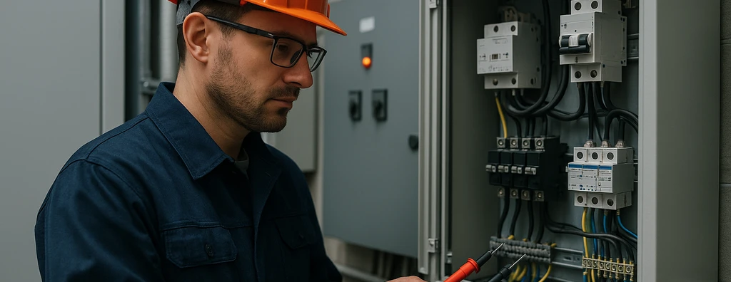
Understand protection against electric shock according to NBR 5410: basic protection, automatic disconnection, grounding, equipotential bonding, RCDs, SELV/PELV, and verification.
Check it out!
The protection against electric shock combines engineering measures intended to prevent dangerous contact with live parts and limit the consequences of faults that may energize exposed conductive parts and other accessible conductive elements. In low-voltage installations, it does not depend on a single device: it results from the combination of circuit design, insulation, barriers, grounding, equipotential bonding, automatic disconnection, protective devices, environmental conditions, and operation and maintenance procedures.
ABNT NBR 5410 structures this protection in layers. Basic protection applies under normal conditions; fault protection reduces risk when a basic measure is no longer sufficient; and certain situations require additional protection. The required level of protection also depends on external influences, the competence of persons, the presence of water, contact with conductive elements, and installation characteristics.
For this reason, treating shock protection merely as “installing an RCD” or “providing grounding” is technically insufficient. The design should verify how the different measures work together and whether operating times, fault-current paths, protective conductors, equipotential bonding, and selected devices produce an effectively safe condition.
In existing installations, the assessment needs to consider actual field conditions, available documentation, and changes accumulated over time. Outdated diagrams, interrupted protective conductors, improper neutral-to-PE connections, incompatible RCDs, and changes made without design review may compromise measures that were originally adequate.
What Is Protection against Electric Shock?
Protection against electric shock is the set of measures that reduces the probability of a person coming into contact with a dangerous voltage and limits the duration or intensity of exposure when a fault occurs.
The logic begins by preventing accidental access to live parts. Basic insulation, enclosures, and barriers are examples of measures that prevent contact during normal operation. The design must then consider what happens if insulation fails and an exposed conductive part becomes energized.
Under this condition, the protective conductor, equipotential bonding, grounding arrangement, and operation of the device responsible for automatic disconnection become decisive. The relationship among these elements is addressed more broadly in the article on NBR 5410.
Basic Protection and Fault Protection
Basic protection seeks to prevent contact with live parts under normal conditions. It can be achieved through appropriate insulation, barriers, enclosures, and other provisions specified for the application.
Fault protection considers that a defect may make a dangerous potential accessible. The general protective measure indicated by NBR 5410 is equipotential bonding associated with automatic disconnection of supply. This requires exposed conductive parts and relevant elements to be properly interconnected and the fault current to be sufficient to cause the protective device to operate within the required conditions.
This approach explains why the electrical grounding system cannot be assessed solely by an isolated resistance value. Continuity of protective conductors, connections, the adopted TN, TT, or IT grounding arrangement, and protective-device characteristics are all part of the same engineering problem.
Automatic Disconnection, Grounding, and Equipotential Bonding
With automatic disconnection, a fault that connects a live part to an exposed conductive part should result in sufficiently rapid disconnection to limit risk. The way this condition is verified varies according to the TN, TT, or IT grounding arrangement.
In TN systems, fault-loop impedance and protective-device characteristics are central to operation. In TT systems, residual-current protection plays a particularly important role in protection by automatic disconnection. In IT systems, continuity of service may be preserved on the first fault, but the design should consider insulation monitoring and the condition of a second fault.
Equipotential bonding equipotential bonding reduces dangerous potential differences between exposed conductive parts and simultaneously accessible conductive elements. When the conditions of the general measure cannot be fully met or specific locations require reinforcement, NBR 5410 provides for supplementary equipotential bonding.
What Is the Role of an RCD in Protection against Electric Shock?
A residual current device detects imbalance among currents flowing through the live conductors of the circuit and can interrupt the supply when the residual current reaches the operating threshold.
NBR 5410 recognizes devices with a rated residual operating current of up to 30 mA as additional protection against electric shock in specified situations. The standard itself makes clear that this additional protection does not, by itself, constitute a complete protective measure and does not replace the other protective measures.
This is important because the presence of an RCD, RCCB, or RCBO does not, by itself, correct a missing protective conductor, deficient equipotential bonding, an incorrect grounding arrangement, or a poorly designed circuit.
It is also necessary to select type, rated current, sensitivity, and coordination compatible with the loads and expected leakage currents, avoiding both loss of protection and nuisance tripping that harms operational continuity.
Double or Reinforced Insulation
Double or reinforced insulation is another protective measure against electric shock. With double insulation, basic protection and supplementary protection are provided by separate layers; with reinforced insulation, a single insulation solution provides an equivalent level of safety.
Class II equipment is a well-known example of this approach. However, applying the measure to an installation requires preserving the original conditions and preventing later changes that reduce its effectiveness.
For electrical lines and circuits, the decision should not be simplistically extrapolated from the class of a connected device. The design remains responsible for defining the conductors, protections, and infrastructure appropriate to the circuit.
Electrical Separation and SELV/PELV
Individual electrical separation may be used in specific applications when the separated circuit meets the required isolation conditions relative to other circuits and earth and supplies the load within the limits established for the protective measure.
SELV and PELV systems use extra-low voltage and protective separation to reduce risk. One difference between them is grounding: SELV circuits have no intentionally grounded live parts, while PELV systems may be grounded according to their design.
These measures should not be used as a generic justification for dispensing with risk assessment. Voltage, environment, user type, separation between circuits, and source construction are part of the safety criteria.
External Influences Change the Protection Strategy
The same voltage may represent different risk conditions depending on the environment. NBR 5410 classifies external influences such as the presence of water, competence of persons, and degree of contact with conductive parts or earth potential.
Wet areas, places with large public occupancy, industrial environments, maintenance areas, and locations accessible only to instructed or qualified persons require specific design decisions. It is not technically correct to apply the same protective solution to every situation merely because the circuits have the same nominal voltage.
This assessment should appear in design documentation, specifications, and inspection and maintenance criteria.
Protection against Electric Shock and NR-10
NR-10 NR-10 addresses safety in electrical installations and services from operational, documentary, and organizational perspectives. The regulatory standard and technical standards do not perform the same function, but complement each other in electrical-risk management.
Safe design, up-to-date diagrams, circuit identification, procedures, training, control measures, documentation, and the required records where applicable need to reflect the actual condition of the installation. The Electrical Installation Safety Dossier is one of the relevant documentation routes for installations subject to the corresponding requirements.
How to Verify Whether Protection Remains Effective?
Design compliance alone does not guarantee that the condition remains adequate throughout the service life. Changes, expansions, maintenance interventions, and connection degradation may alter system behavior.
Verification may involve visual inspection, continuity of protective conductors and equipotential-bonding connections, functional tests of residual-current devices, assessment of automatic disconnection, circuit identification, condition of switchboards, and comparison between documentation and the installed condition.
When there are doubts about the actual installation, an electrical installation inspection can turn field findings into a diagnosis, corrective priorities, and design or documentation needs.
When Should an Installation Be Reviewed or Upgraded?
Review is advisable when there are renovations or expansions, a change of use, significant load changes, recurring trips, component overheating, lack of documentation, successive interventions without design updates, accidents or near misses, or a need to update safety documentation.
The engineering path normally starts from the actual condition: survey, diagnosis, risk classification, definition of corrective measures, design when needed, controlled execution, testing, document updates, and acceptance.
Conclusion
Protection against electric shock is not an isolated component but a safety architecture. Insulation, barriers, protective conductors, grounding, equipotential bonding, automatic disconnection, RCDs, electrical separation, and extra-low voltage perform different functions and need to be applied under the conditions specified for each measure.
A reliable installation is one in which the protective rationale can be demonstrated by design, verified in the field, and maintained throughout the lifecycle. When an existing installation does not provide this traceability, the first step is to diagnose the actual condition and rebuild the technical basis required for corrective action.
Technical References
[1] BRAZILIAN ASSOCIATION OF TECHNICAL STANDARDS. ABNT NBR 5410 — Low-voltage electrical installations. Consult the current edition in the ABNT Catalog.
[2] BRAZIL. Ministry of Labor and Employment. NR-10 — Safety in Electrical Installations and Services. Consult the official text at the MTE.
[3] INTERNATIONAL ELECTROTECHNICAL COMMISSION. IEC 61140:2016 — Protection against electric shock — Common aspects for installation and equipment. Consult the official publication in the IEC Webstore.
Frequently Asked Questions
As a general protective measure, NBR 5410 adopts equipotential bonding associated with automatic disconnection of supply. Other measures are applied under specific conditions or as reinforcement.
No. A high-sensitivity RCD is recognized as additional protection in specified situations and does not replace other protective measures, including the protective conductor, grounding, and equipotential bonding where applicable.
Basic protection prevents dangerous contact with live parts under normal conditions. Fault protection limits risk when a fault causes exposed conductive parts or other conductive elements to become dangerously energized.
No. The protective principle may be common, but verification of automatic disconnection and the devices involved depend on the grounding arrangement and circuit characteristics.
Renovations, expansions, changes of use, lack of documentation, recurring trips, overheating, accidents, near misses, and successive interventions without design review are typical situations that justify inspection and diagnosis.
Complementary Technical Materials
Related Solutions
- Electrical Safety and NR-10 Compliance
- Low-Voltage Electrical Infrastructure
- Grounding and Equipotential Bonding
- Surge Protection Measures
Related Engineering Services
- Electrical Installation Inspection
- Detailed Technical Report on Electrical Installations
- Electrical Installation Safety Dossier — PIE
- Low-Voltage Electrical Design
- Short-Circuit, Selectivity, and Protection Coordination Study
- Commissioning and Acceptance of Electrical Installations
Related Technical Content
- NBR 5410
- RCD, RCCB, and RCBO
- TN, TT, and IT Grounding Arrangements
- Electrical Grounding
- Equipotential Bonding
- NR-10: Safety in Electrical Installations and Services
- Electrical Installation Safety Dossier — PIE
- Electrical Safety
