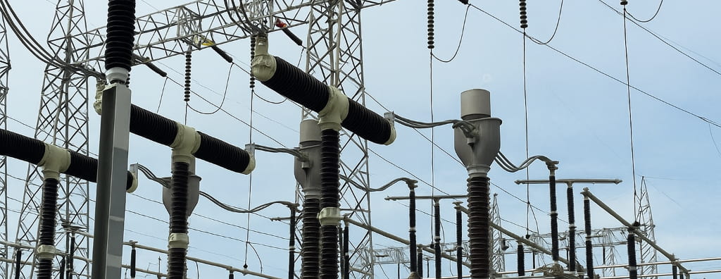
Criteria for monitoring disconnect switches in substations, including signals, visual confirmation, SCADA, remote assistance, testing, and normative applicability.
Check it out!
Monitoring disconnect switches in substations needs to be defined according to the equipment function, operating regime, and level of evidence required for each switching operation. It is not simply a matter of installing a camera facing the switchyard or receiving a position contact in the supervisory system.
A reliable solution combines electrical signals, logical states, images, event records, telecommunications, auxiliary power, and operating procedures. Each layer answers a different question: was the command sent? Did the mechanism move? Did the auxiliary contacts change state? Did the blade reach the expected position? Was the observed condition recorded with a coherent date and time?
Remote assistance can use this evidence to support remote operation, but its applicability is not universal. The design must verify the installation classification, requirements of the responsible agent, applicable Grid Procedures, internal standards, and risks associated with switching operations.
This article presents technical criteria for structuring disconnect-switch monitoring without confusing remote indication, physical confirmation, video monitoring, and remote assistance.
What Does It Mean to Monitor a Disconnect Switch?
Monitoring a disconnect switch means obtaining enough information to determine its state, recognize abnormal conditions, and support an operational decision. Information may come from auxiliary contacts, sensors, IEDs, relays, RTUs, supervisory systems, images, or local inspection.
The architecture should not assume that all these sources are equivalent. An auxiliary contact normally indicates the state of the mechanism or an associated element. An image may show the apparent blade position. SCADA records states and alarms. The operating procedure defines how evidence will be interpreted before, during, and after a switching operation.
Position indication is not the same as physical confirmation
The “open” or “closed” indication received at the control center depends on the chain formed by contacts, cabling, input modules, logic, communications, and supervisory interface. A failure at any point can generate incorrect, frozen, or unavailable information.
Visual confirmation adds independent evidence, but it also has limitations. An inadequate angle, reflections, rain, low light, dirt, obstruction, vibration, or loss of resolution can prevent reliable position assessment.
Engineering must therefore establish which sources are primary, which are complementary, and how discrepancies will be handled.
Open, closed, and intermediate states
The design should consider more than two states. During a mechanical failure, improper adjustment, or interruption of movement, the switch may remain in an intermediate position. There may also be differences between the actuator mechanism position and the actual pole position.
Whenever criticality justifies it, the logic should distinguish open, closed, intermediate, pole discrepancy, command failure, loss of power, loss of communication, and unavailability of visual confirmation.
When Monitoring Is Necessary
The need for monitoring should be defined through functional and risk analysis. It tends to be greater when the switch participates in remote switching, isolation of critical equipment, system restoration, bus transfer, maintenance, interlocking, or operations without permanent local staff.
The impact of an incorrect indication, switching frequency, travel time to the installation, possibility of local inspection, system redundancy, and consequences for people, equipment, and continuity should also be considered.
There is no valid technical rule stating that every disconnect switch in every substation needs a camera. In some cases, reliable signals and local procedures are sufficient. In others, independent visual or sensor confirmation is an important part of the operating regime.
Operational monitoring needs to be designed as a chain of evidence, not as an isolated set of cameras.
The solution should coordinate field signals, automation, telecommunications, images, auxiliary power, records, and procedures so that each item of information has a defined function in operations.
Learn about the remote-assistance and operational-monitoring solution for substations
Remotely assisted installations
In installations operated without permanent local staff, remote assistance organizes resources so that the substation remains operationally assisted from another location. This may involve supervision, telecommunications, video, alarms, access control, communication with field teams, and contingency procedures.
Switch monitoring may be part of this architecture, but it does not define remote assistance by itself. The solution needs to consider the entire chain required to recognize events, assess conditions, authorize actions, follow switching operations, and respond to failures.
Applicability of ONS Grid Procedures
ONS Grid Procedures must be analyzed according to the agent, the function of the installation, its classification within the Operation Grid, its classification, and the applicable operating regime. Requirements intended for transmission facilities or specific agents should not be generalized to every primary cabinet, industrial substation, or distribution installation.
Verification should consider the current versions of the applicable submodules, project-specific requirements, and the installation owner’s documents. ANEEL Normative Resolution No. 1,000 should not be used as the central basis for defining remote assistance or disconnect-switch position confirmation.
Technical Monitoring Architecture
A robust architecture separates functions and maintains traceability across field, automation, network, and control center. The design should show the origin of each signal, the information path, equipment power supply, supervision points, and expected behavior in the event of failure.
Position signals and sensors
Auxiliary contacts, limit switches, position sensors, and actuator mechanisms form the first information layer. The design should verify the number of contacts, normal or inverted logic, circuit supervision, control voltage, cable identification, environmental conditions, and integration with the control panel.
When there are three independent poles or mechanisms that may become discrepant, individual monitoring should be evaluated. Combining the poles into a single state may conceal a relevant anomaly.
IEDs, RTU, local control system, and SCADA
Field signals are processed by IEDs, relays, controllers, RTUs, or local supervision and control systems. Engineering should define addressing, data quality, time stamps, alarms, events, commands, permissives, interlocks, and handling of communication loss.
In SCADA, the interface needs to present states unambiguously. Colors, symbols, and text should be consistent with the operating standard. Stale or invalid-quality information must not be displayed as if it were a confirmed state.
Operational monitoring by video
Video should be designed for a specific technical purpose. The camera needs to show the element whose condition will be evaluated, with resolution, field of view, contrast, and illumination compatible with the expected decision.
For disconnect switches, the scene may need to show all three poles, the mechanism, blade, fixed contact, and visual references that make the position recognizable. A panoramic switchyard view may be useful for context, but generally does not replace a dedicated scene when confirmation requires detail.
The analysis should consider:
- camera position and height;
- distance and angle relative to the equipment;
- occlusions caused by structures, insulators, and other poles;
- daytime, nighttime, and emergency lighting;
- reflections, backlighting, and solar variation;
- rain, fog, dirt, and condensation;
- vibration, wind, and support stability;
- useful resolution on the object of interest;
- latency, availability, and transmission quality;
- recording, retention, and time synchronization.
Telecommunications and time synchronization
Remote confirmation depends on the network. The design should size bandwidth, latency, redundancy, segregation, quality of service, addressing, management, and contingency paths.
Video, states, and event records need to share a coherent time reference. Without adequate synchronization, it becomes difficult to correlate the command, contact changes, observed movement, and recorded alarms.
Auxiliary power and grounding
Cameras, switches, converters, servers, input modules, and communication equipment need to remain available under the conditions in which they will be used. The architecture should consider AC or DC power, redundant supplies, UPS systems, battery banks, autonomy, protection, selectivity, and supervision.
The installation should also coordinate grounding, equipotential bonding, shielding, surge protection, and electromagnetic compatibility. Failures at these interfaces can cause unavailability precisely during switching events or electrical faults.
How Visual Confirmation Should Be Used
An image is complementary operational evidence. It can help confirm movement, identify apparent position, recognize obstructions, verify environmental conditions, and support field teams.
However, video should not automatically be treated as a replacement for auxiliary contacts, interlocks, sensors, SCADA signaling, or local inspection. The role of each type of evidence needs to be documented.
Local switching with remote assistance
When a team performs the switching operation on site with remote support, video can allow the control center to follow the sequence, confirm compliance with the procedure, and maintain communication with field personnel.
The procedure should establish responsibilities, operating phrases, confirmation points, interruption of the activity in the event of discrepancies, and recording of critical steps.
Remote switching
In remote switching, the chain includes equipment selection, permissives, interlocks, command, mechanism actuation, signal changes, and confirmation of the result. The design needs to define waiting times, failure alarms, repeat-command blocking, and response to discrepant states.
The presence of video does not eliminate the need for safe logic. A delayed, frozen, or unavailable image cannot be interpreted as valid confirmation.
Discrepancy between signals and image
When SCADA indicates one position and the image suggests another, the condition should be treated as an anomaly. The procedure may require blocking new switching operations, contacting the local team, inspection, circuit verification, or use of additional evidence.
The design should include an alarm for video unavailability and monitoring of the monitoring infrastructure itself. No image, a displaced camera, or loss of recording are system failures and need to be identified.
Design Methodology
A disconnect-switch monitoring design should begin with operating scenarios, not camera selection. The recommended sequence is to understand the installation, classify switching operations, define the required evidence, and only then develop the architecture.
Field survey
The survey should record switchyard arrangement, equipment, mechanisms, panels, existing signals, infrastructure, lighting, power supply, telecommunications, routes, environmental conditions, and installation constraints.
Photographs and field models help in studying scenes, but final validation needs to occur on site. Small angle differences can determine whether the position is recognizable or not.
Equipment and evidence matrix
For each switch, it is useful to record function, criticality, actuation method, poles, available contacts, SCADA signals, need for video, planned scene, operating mode, and contingency behavior.
This matrix avoids applying the same solution to equipment with different functions and facilitates traceability from requirement through design, deployment, and testing.
Scene design
Each scene should have a verifiable objective. “View the switchyard” is a generic requirement. “Allow the operator to distinguish all three poles as open, closed, or intermediate under daytime and nighttime conditions” is a testable requirement.
The design should define camera, lens, support, environmental protection, lighting, resolution, framing, and recording parameters. When necessary, complementary scenes or controlled overlap may be specified.
Integration and documentation
Architecture diagrams, signal lists, addressing, network topology, power supply, installation details, cause-and-effect matrix, test procedures, and acceptance criteria need to represent the integrated solution.
Responsibilities for automation, telecommunications, video, civil works, panels, control center, and cybersecurity should also be defined. Many failures occur at interfaces between disciplines rather than in isolated equipment.
Testing, Commissioning, and Acceptance
Acceptance should demonstrate that the system works under actual operating conditions. Testing only the image on a bench or only the contact at the panel does not prove the complete chain.
FAT
Factory tests can verify configuration, logic, screens, addressing, recording, alarms, access profiles, and simulated integration. FAT reduces rework but does not replace testing in the installed environment.
SAT and functional tests
On site, field of view, equipment position, daytime and nighttime conditions, commands, contacts, alarms, loss of communication, loss of power, recovery, synchronization, and recording should be tested.
Whenever possible, testing should reproduce the defined operating scenarios. The criterion is not merely “there is an image,” but “the required evidence can be obtained consistently.”
End-to-end testing
End-to-end testing follows the entire sequence: command at the control center, transmission, field actuation, state change, image, time stamp, alarm, recording, and presentation to the operator.
The test should also verify failure conditions such as unavailable camera, invalid state, interrupted communication, or discrepancy between sources.
Acceptance criteria should be defined before deployment.
When FAT, SAT, functional tests, and end-to-end tests are planned only at the end, interface failures among automation, video, network, and operations tend to appear too late.
Learn about the commissioning and technical acceptance service for electrical installations
Common Design Errors
Among the most frequent errors are:
- installing one panoramic camera and assuming it confirms any equipment;
- stating that every substation requires visual confirmation without assessing applicability;
- using only the mechanism indication to represent pole position;
- failing to provide for intermediate or discrepant states;
- ignoring lighting, reflections, and weather conditions;
- failing to synchronize video and events;
- sharing a network without assessing bandwidth, latency, and segregation;
- powering the system without autonomy compatible with its function;
- treating security video surveillance and operational monitoring as the same system;
- performing acceptance without end-to-end testing;
- failing to define the procedure for discrepancies between signals and image.
Technical Application Example
Consider a motor-operated three-pole disconnect switch used to isolate a bus section in a remotely operated substation. The mechanism has open and closed contacts, while the control center receives states through an RTU.
The analysis identifies that the consequence of an incorrect indication is significant and that travel time to the installation is long. The design establishes four pieces of evidence: auxiliary contacts, supervision of motor power supply, a dedicated scene showing all three poles, and synchronized recording of the command and events.
During testing, the closed position is found to be easily recognizable during the day, but the existing floodlight causes glare at night. Acceptance is not completed merely because the camera transmits an image. The design adjusts lighting and framing until all three poles can be assessed under the intended conditions.
This example demonstrates that engineering is not limited to specifying a camera. The requirement needs to be converted into a verifiable condition and validated in the actual environment.
Disconnect-Switch Monitoring Within Remote Assistance
Disconnect-switch monitoring is a subsystem within a broader architecture. Operating a substation under a remote-assistance regime may also require electrical supervision, redundant telecommunications, communication with teams, access control, alarms, physical security, auxiliary services, cybersecurity, and contingency procedures.
The solution should be proportional to the risk and classification of the installation. The objective is not to multiply equipment, but to build reliable evidence, clear interfaces, and an operating model capable of recognizing and handling abnormal conditions.
A3A Engenharia develops integrated remote-assistance and operational-monitoring designs, connecting automation, video, telecommunications, auxiliary power, and commissioning. The scope may include survey, architecture, detailed design, specifications, deployment, integration, and testing according to the responsibilities defined for each project.
Technical references
[1] ONS. Current Grid Procedures.
[2] ONS. Submodules 2.2, 2.15, and 2.16 of the Grid Procedures.
[3] ABNT. ABNT NBR IEC 62676 series — Video surveillance systems for use in security applications.
[4] ABNT. ABNT NBR IEC 61850-10 — Communication networks and systems for power utility automation.
Frequently asked questions
No. The need depends on equipment function, operating regime, risks, owner standards, and requirements applicable to the installation. In some cases, images are important complementary evidence; in others, signals and local procedures may be sufficient.
SCADA indication represents the state received through the chain of contacts, modules, logic, and communications. It is not necessarily an independent physical confirmation of pole position.
No. Video should be treated as complementary evidence. Contacts, sensors, interlocks, command logic, and operating procedures remain necessary according to the function and criticality of the switching operation.
Remote control is the remote transmission of commands. Remote assistance is the set of resources and procedures that keeps the installation operationally assisted from another location and may include supervision, video, communications, alarms, and field-team support.
Acceptance should test the end-to-end chain, including command, actuation, state changes, image, synchronization, alarms, recording, communication loss, and contingency conditions. The mere presence of an image does not demonstrate compliance with the requirement.
Complementary technical materials
Solutions
- Remote Assistance and Operational Monitoring in Substations
- Medium-Voltage Electrical Installations
- Perimeter Protection
Engineering services
- Medium-Voltage Substation and Primary Cabinet Design
- Commissioning and Technical Acceptance of Electrical Installations
- Short-Circuit, Selectivity, and Protection Coordination Study
- Grounding Design
- Grounding Technical Report and Measurements
Complementary technical materials
- Substation Remote-Assistance Design
- Remote Assistance in Substations: concepts and requirements
- Telecommunications Design for Substations
- What Is SCADA in the Power Sector?
- Security in Power-System Automation Networks
