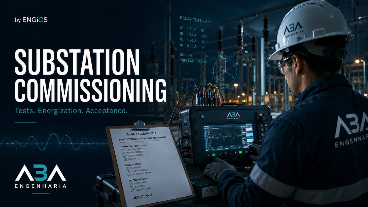
Understand substation commissioning: planning, FAT, SAT, electrical testing, protection, controlled energization, acceptance, and documentation.
Check it out!
Substation commissioning is the structured verification, testing, integration, and documentation process used to demonstrate that the installation was designed, supplied, assembled, and configured according to technical requirements and is prepared to enter service safely and with predictable performance.
It is not limited to performing a few tests before energization. The process begins with requirements definition, passes through design review, factory testing, equipment receipt, installation inspections, field testing, functional and integrated testing, energization preparation, and consolidation of acceptance evidence.
In a substation, apparently small failures can combine: an incorrect CT ratio, a reversed trip circuit, a protection setting not loaded, an incomplete interlock, a switch not indicated in SCADA, or a missing grounding connection. Commissioning seeks to identify these conditions before the asset is placed in service.
What is substation commissioning?
Commissioning a substation means verifying, in a planned and traceable manner, whether each system and the integrated installation perform their intended functions.
In practice, the process connects design engineering to the actual installed condition. Owner requirements, diagrams, electrical studies, and manufacturer documentation form the baseline against which electromechanical assembly, power and control circuits, auxiliary systems, grounding, and primary equipment are verified.
A second layer addresses functions that depend on integration: relays and IEDs, interlocks, automation, SCADA, telecommunications, synchronization, and interfaces with control centers. Equipment approved in isolation does not, by itself, demonstrate that the complete protection, control, supervision, and communication chain will operate correctly in service.
Finally, the results of electrical tests, functional tests, and integrated tests must be associated with acceptance criteria, open items, and documentation of the delivered configuration. The Complete Guide to Commissioning positions this logic within the broader process of planning, readiness, testing, acceptance, and handover.
The expected result is not merely a collection of reports. It is a technical conclusion supported by evidence, indicating which systems are fit for service, which have restrictions, and which open items prevent operation.
Commissioning, pre-commissioning, startup, and energization
These terms are related, but they are not equivalent.
Pre-commissioning
Pre-commissioning concentrates verifications performed before complete functional testing and energization. In substations, it is the stage in which basic errors in assembly, identification, continuity, insulation, grounding, and documentation should be eliminated before the process advances to broader functional demonstrations. The article on Pre-Commissioning in Engineering details systemization, readiness, test packs, and the Mechanical Completion gate. Depending on scope, it includes:
- physical inspection of the installation;
- inspection of identification and terminations;
- circuit continuity;
- insulation resistance;
- verification of documented torque;
- technical cleaning;
- grounding verification;
- polarity and ratio verification;
- initial validation of inputs and outputs;
- review of documentation and certificates.
Its objective is to prepare the system for subsequent tests and eliminate basic construction defects.
Commissioning
Commissioning covers functional validation of equipment and systems. It verifies whether components operate individually, interfaces function, and the integrated installation responds according to the design philosophy.
Startup
Startup is the initial placing of equipment or processes into operation. In a substation, it may relate to starting auxiliary systems, servers, chargers, ventilation, supervision, or specific equipment.
Energization
Energization is the application of voltage to the installation or part of it. It is a critical operational milestone and must occur only after the prerequisites defined in the energization plan have been met.
This article does not present a field switching sequence. Energization requires authorized and qualified personnel, an approved formal procedure, coordination with operations, risk assessment, and compliance with the rules of the facility and the applicable utility or system operator.
Technical acceptance
Technical acceptance is the documented decision regarding installation compliance and fitness for service. It may be total, partial, provisional, conditional, or rejected, depending on the contract and the nature of open items.
When should commissioning begin?
Commissioning should be considered during the design phase. Starting only after construction is complete reduces the ability to prevent failures and turns the process into a race to test what has already been built.
During engineering, the following should be defined:
- owner requirements;
- acceptance criteria;
- system and subsystem matrix;
- supply boundaries;
- testing responsibilities;
- hold and inspection points;
- required documentation;
- test resources;
- interfaces with the utility, ONS, or control center;
- energization philosophy;
- record format;
- treatment of open items;
- requirements for assisted operations.
Early planning allows the design to incorporate test points, terminals, test switches, isolation resources, indications, access, and documentation required for future commissioning.
Commissioning plan
The commissioning plan organizes the process and prevents tests from being performed without sequence, criteria, or traceability.
More important than accumulating checklist items is organizing the plan into decision blocks. It should show what will be commissioned, which boundaries and dependencies exist, who is responsible for execution and acceptance, which procedures and resources will be used, and what evidence will allow each stage to be released.
| Plan dimension | Main content |
|---|---|
| Governance | objectives, boundaries, responsibilities, hold points, and decision authority |
| Systemization | systems, subsystems, interfaces, dependencies, and release sequence |
| Testing strategy | procedures, instruments, safety, FAT, SAT, functional and integrated testing |
| Readiness and acceptance | entry and exit criteria, evidence, open items, energization, handover, and assisted operations |
This structure allows the schedule and documentation to follow the actual maturity of the systems. A bay may have advanced physical installation and still not be ready for testing because protection settings, DC supply, communication, approved procedures, or safety conditions are missing.
The plan must distinguish equipment testing, circuit testing, functional testing, and integrated testing. A circuit breaker may be mechanically approved and still fail in the complete protection and trip chain.
The energization gate must be supported by evidence, not by percentage of physical construction complete.
When the owner requires independent verification, the scope may integrate document review, inspections, electrical tests, protection and automation testing, open items, readiness, and a technical acceptance recommendation.
Structure testing, readiness, energization, and acceptance on a single evidence base →
System and subsystem matrix
Dividing the substation into systems makes completeness control easier. A matrix may include:
- line or feeder entrance;
- busbars;
- line, transformer, feeder, and bus-coupler bays;
- power transformers;
- circuit breakers and disconnect switches;
- CTs, VTs, and CVTs;
- surge arresters;
- power cables;
- grounding grid;
- protection and control;
- AC auxiliary services;
- DC system, batteries, and rectifiers;
- SCADA, RTU, or SAS;
- IEC 61850 network;
- telecommunications;
- time synchronization;
- CCTV and remote assistance, when included in scope;
- fire protection and associated building systems.
Each subsystem must have clear boundaries, associated documents, responsible parties, prerequisites, and completion status.
Requirements and acceptance criteria
A test only produces useful evidence when the acceptance criterion has been defined before execution.
Criteria may derive from:
- applicable technical standards;
- owner specification;
- approved design;
- data sheet;
- manufacturer documentation;
- electrical studies;
- utility requirements;
- ONS Grid Procedures, when applicable;
- contractual requirements;
- protection and operating philosophy.
The expression “equipment working” is insufficient. The criterion must indicate what will be measured, under which condition, with which tolerance, which instrument will be used, and how the result will be recorded.
Document review before testing
Field execution should be preceded by a document review. Relevant documents include:
- single-line diagram;
- three-line and functional diagrams;
- control and protection schematics;
- interconnection diagrams;
- cable and terminal lists;
- signal lists;
- cause-and-effect matrix;
- trip matrix;
- protection philosophy;
- short-circuit and coordination studies;
- relay settings;
- automation architecture;
- SCL files, when applicable;
- network diagrams;
- addressing plan;
- grounding drawings;
- layout and installation drawings;
- manuals and test certificates;
- FAT and SAT procedures;
- as-built documentation.
Conflicting documents must be resolved before energization. Field personnel should not informally decide which revision prevails.
FAT: factory acceptance testing
FAT verifies equipment or systems before shipment or final deployment. In a substation, it reduces the risk of carrying manufacturing, configuration, or integration defects into the field when they could have been detected in a controlled environment. The article FAT and SAT: what they are, differences, integrated testing, and acceptance criteria explores the relationship among factory testing, field testing, evidence, retests, and acceptance decisions.
It may be applied to:
- transformers;
- medium-voltage switchgear;
- circuit breakers;
- relays and protection panels;
- digital supervision and control systems;
- rectifiers and chargers;
- UPS systems;
- auxiliary-services panels;
- gateways and servers;
- integrated automation systems.
The FAT must have an approved procedure, acceptance criteria, appropriate instruments, records, and deviation handling.
For IEC 61850 systems, it may include verification of data models, reports, commands, GOOSE, SCL files, interoperability, redundancy, and performance. ABNT NBR IEC 61850-10 addresses conformance testing, but a conformance certificate does not replace FAT of the actual application.
Equipment receipt and preservation
After delivery, receiving inspection must verify that the supplied equipment corresponds to what was approved and has not suffered damage.
At receipt, the team should confirm equipment identity by nameplate, serial number, and supply documentation, also verifying the specified accessories and spare parts. This check prevents discrepancies in model, ratio, class, capacity, or configuration from being discovered only during testing.
The physical condition must be recorded before installation: enclosures, connectors, terminals, bushings, insulators, seals, fluids, and impact or tilt indicators, when present, provide evidence regarding transportation and storage. Damage or deviations must be segregated and addressed before the equipment is incorporated into the installation.
After receipt, preservation becomes part of quality control. Requirements for anti-condensation heating, humidity control, storage position, periodic inspections, oil or gas preservation, and interface protection must follow manufacturer documentation and remain traceable until installation.
Preservation between receipt and energization must follow manufacturer requirements. Equipment that passed FAT may deteriorate during transportation or improper storage.
Visual and construction inspection
Visual inspection must precede testing. Within its scope, ABNT NBR 14039 establishes that the installation be visually inspected and tested before being placed in service.
The visual inspection must compare the installed condition with the design and safety requirements before test voltages or currents are applied. Equipment and circuit identification, terminations, connections, grounding, barriers, enclosures, lockouts, and cable segregation must be consistent with the current documentation.
Conditions affecting operation and maintenance must also be observed: accessibility, clearances, supports, cleanliness, signage, fire protection, and environmental conditions. An electrically functional installation with unsafe access, ambiguous identification, or documentary discrepancies is not yet in an adequate condition for acceptance.
Inspection does not replace testing, but it prevents the application of test voltage or current to an installation that is visibly incorrect.
Grounding-grid testing
The grounding grid contributes to safety, protection, and the performance of control and telecommunications systems.
Verifications may include:
- continuity of connections;
- inspection of welds and connectors;
- verification of materials and cross-sections;
- connection of structures, equipment, fences, and panels;
- ground resistance, when applicable;
- assessment of step and touch voltages according to the design;
- equipotential bonding;
- interfaces with surge arresters and shields;
- documentation of buried connections.
The ground-resistance value alone does not demonstrate grounding-grid safety. Acceptance must consider the design, potential distribution, fault currents, and applicable criteria.
Power-cable testing
Tests must be defined according to cable type, voltage, accessories, length, and applicable recommendations.
They may involve:
- identification and phasing;
- continuity;
- insulation resistance;
- shield verification;
- jacket integrity;
- appropriate dielectric tests;
- inspection of terminations and splices;
- shield grounding;
- verification of bend radius and support;
- comparison with installation records.
The test voltage and method should not be chosen generically. Inappropriate tests may fail to detect the relevant defect or may unnecessarily stress a cable or accessory.
Power-transformer commissioning
The scope depends on equipment rating, technology, voltage, and condition.
It may include:
- identification and nameplate data;
- installation inspection;
- verification of bushings and accessories;
- turns ratio;
- winding resistance;
- polarity and vector group;
- excitation current;
- insulation resistance;
- power factor or dissipation factor, when applicable;
- insulating-oil analysis;
- tap-changer verification;
- sensors and indicators;
- cooling system;
- alarms and trips;
- protection circuits;
- tank and neutral grounding;
- SCADA integration;
- energization conditions and inrush current.
Results must be compared with factory data, manufacturer limits, history, and design criteria.
Circuit-breaker commissioning
Circuit-breaker verification may include:
- identification and rated characteristics;
- installation and alignment;
- pressure, density, or condition of the interrupting medium;
- operating mechanism;
- opening and closing times;
- pole simultaneity;
- contact resistance;
- trip and close coils;
- motors and charging systems;
- auxiliary contacts;
- lockouts and alarms;
- trip circuits;
- local and remote control;
- integration with protection and supervision;
- operation counter;
- grounding and mechanical safety.
Individual testing must be complemented by trip-chain testing, from the relay or command to position confirmation.
Commissioning of disconnect switches and grounding switches
Verifications may include:
- alignment and travel;
- main contacts;
- manual and motorized mechanisms;
- limit switches;
- auxiliary contacts;
- mechanical and electrical interlocks;
- local and remote control;
- position indication;
- SCADA integration;
- grounding switch;
- structure grounding;
- force and behavior of the mechanical transmission.
Remote indication must correspond to the actual equipment position. For remotely assisted installations within the applicable scope, additional requirements may result from the Grid Procedures and the applicable operating philosophy.
CT and VT commissioning
Instrument transformers affect protection, metering, and supervision.
Verification may involve:
- identification and ratio;
- polarity;
- continuity;
- insulation resistance;
- class and connected burden;
- secondary circuits;
- single-point grounding of the secondary;
- safe short-circuiting of CTs during interventions;
- fuses and protection of VT circuits;
- phase correspondence;
- connections to relays, meters, and SCADA;
- validation of signals and scaling.
Polarity or ratio errors may remain invisible during simple inspections and compromise protection functions.
Protection, control, and relay settings
Protection commissioning must verify implementation of the philosophy defined in the approved studies and documents.
Possible activities include:
- verification of model and firmware;
- loading and recording settings;
- verification of inputs and outputs;
- secondary injection;
- testing protection elements;
- curves and time delays;
- blocking and permissive logic;
- trip matrix;
- breaker failure;
- reclosing, when applicable;
- synchronism and circuit supervision;
- oscillography and records;
- communication among IEDs;
- end-to-end tests;
- confirmation of operation on the correct equipment.
Approval of a settings file does not prove that it was loaded into the correct IED or that output circuits were wired according to the design.
AC and DC auxiliary systems
Protection and control depend on auxiliary power. Commissioning must consider:
- normal, alternate, and emergency AC sources;
- auxiliary transformers;
- essential panels and circuits;
- battery banks;
- rectifiers and chargers;
- DC distribution;
- UPS systems and inverters;
- loss-of-supply alarms;
- insulation monitoring;
- autonomy;
- selectivity;
- source transfer;
- redundant supply to critical equipment.
Integrated tests must demonstrate behavior during loss of one source without creating unsafe conditions or unplanned unavailability.
SCADA, RTU, SAS, and IEC 61850
The automation system must be verified from the field point through the operator interface.
The scope may include:
- signal list;
- scales and units;
- single and double indications;
- commands and selections;
- data quality;
- alarms;
- sequence of events;
- time stamping;
- synchronization;
- screens and symbols;
- command permissions;
- gateways;
- communication with the remote control center;
- server and network redundancy;
- behavior during failures;
- records and histories.
For IEC 61850, testing may also include:
- MMS;
- GOOSE;
- Sampled Values;
- datasets and reports;
- publishing and subscription;
- SCL files;
- PRP or HSR;
- PTP synchronization;
- latency and performance;
- behavior under contingency.
ONS Submodule 2.12 establishes supervision and control requirements for installations within its stated scope. These requirements should not be generalized to every substation.
Telecommunications and synchronization
System availability may depend on internal networks and external links.
Verifications may include:
- optical fibers and terminations;
- optical power;
- identification and routes;
- switches and routers;
- VLANs and priorities;
- redundant paths;
- redundancy protocols;
- firewalls and communication rules;
- time synchronization;
- GNSS receivers;
- PTP, NTP, or IRIG-B;
- links with control centers;
- failure alarms;
- auxiliary power supply to equipment.
Testing connectivity alone is not sufficient. Performance, redundancy, recovery, and compliance with the approved architecture must also be verified.
Functional and integrated testing
Functional testing verifies whether equipment or a function responds as expected. Integrated testing verifies the complete chain across systems.
Examples of integrated tests include:
- protection operation, circuit-breaker trip, and indication in SCADA;
- remote command, interlocking, and position confirmation;
- loss of auxiliary supply and alarm generation;
- link failure and switchover to a redundant path;
- transfer between AC sources;
- loss of synchronization and degraded-state indication;
- operation of transformer sensors and associated logic;
- breaker failure and backup trips;
- transfer of events to the control center.
These tests must be planned so as not to expose people or equipment to unnecessary risks. Simulations, test blocks, and controlled environments should be used according to the approved procedure.
End-to-end testing
End-to-end tests validate functions that span different equipment, networks, or facilities.
They may be required for:
- line protection;
- teleprotection;
- line differential protection;
- special protection schemes;
- communication between substations;
- integration with the control center;
- synchronization among devices;
- functions distributed through GOOSE.
The test must consider time, direction, polarity, logic, channel availability, and behavior under contingency.
Preparation for energization
Energization should not be treated as an automatic continuation of construction. It requires a formal decision based on evidence.
Before release, the following must be defined and verified, according to scope:
- physical energization boundaries;
- approved documentation;
- updated diagrams;
- completed tests;
- released settings;
- protections in service;
- functional trip circuits;
- available auxiliary systems;
- controlled temporary grounds;
- validated interlocks;
- communication with operations;
- permits and authorizations;
- classified open items;
- contingency plan;
- team and responsibilities;
- release records.
A long list of completed tests does not compensate for the absence of a critical protection function or a reliable trip circuit.
Readiness meeting and go/no-go decision
The readiness meeting consolidates the status of the installation and records the decision whether to proceed.
It should assess:
- completion by system;
- blocking open items;
- residual risks;
- operations availability;
- emergency resources;
- documentation;
- energization authorization;
- external interfaces;
- relevant weather or operating conditions;
- ability to return to a safe condition.
The decision must identify the responsible parties. Schedule pressure does not turn a blocking open item into an acceptable one.
Controlled energization
Energization must follow a specific procedure prepared for the installation and approved by the responsible parties. The procedure must consider the actual configuration, responsibility boundaries, authorized switching sequence, protection systems, observation points, and interruption criteria.
During energization, the team must monitor the planned quantities and states while maintaining communication with those responsible for operations.
Abnormal conditions must be handled according to the approved plan. Improvised changes to protection, blocking critical functions, or repeating switching operations without technical analysis are not appropriate.
Post-energization verifications
After voltage is applied, the following may be verified, depending on the installation:
- voltages and phase sequence;
- currents and loading;
- abnormal noise and vibration;
- leaks;
- temperatures;
- alarms;
- state indications;
- stability of auxiliary services;
- synchronization;
- communication;
- transformer behavior;
- magnetizing currents;
- quality of records;
- absence of abnormal discharges or heating.
Some verifications require an observation period and monitoring under different load conditions.
Assisted operations
Assisted operations allow the asset to be monitored during the initial period and integration failures that do not appear in static tests to be corrected.
It may include:
- alarm monitoring;
- event monitoring;
- review of authorized fine adjustments;
- support for the operations team;
- treatment of remaining open items;
- report validation;
- document updates;
- training;
- consolidation of the initial operating history.
Assisted operations should not be used to transfer to operations a system that still lacks minimum safety and reliability conditions.
Open-item management
Every nonconformity must be recorded with description, location, evidence, responsible party, deadline, and closure criterion.
A practical classification may separate:
- blocking: compromises safety, protection, operation, or essential compliance and prevents energization or acceptance;
- restrictive: allows limited operation under a formal condition and specific control;
- non-blocking: does not compromise entry into service but requires a deadline and responsible party;
- documentary: related to records, drawings, certificates, or traceability;
- improvement: does not constitute noncompliance but may improve performance or maintenance.
The classification must be contractually defined. An apparently minor open item may be critical when it affects a protection chain.
Provisional, conditional, and final acceptance
Acceptance may take different forms.
Provisional acceptance
Recognizes that the system has reached the defined condition for a stage while maintaining outstanding obligations and an observation period.
Conditional acceptance
Allows operation under formally defined conditions, restrictions, compensating measures, or controls. It must not be used to accept unevaluated risk.
Final acceptance
It is issued after contractual criteria have been met, applicable open items have been closed, and final documentation has been delivered.
The decision must clearly indicate what was accepted, which limits remain, and which responsibilities continue in force.
Conditional acceptance is defensible only when the exception is identified, assessed, and traceable.
Criteria defined before testing, evidence linked to requirements, and classified open items make it possible to distinguish an acceptable residual item from a condition that must block energization, operation, or receipt.
Handover documentation
The commissioning dossier may include:
- commissioning plan;
- system matrix;
- approved procedures;
- inspection records;
- calibration certificates;
- FAT reports;
- field-test reports;
- protection settings;
- configuration files;
- trip and interlock matrices;
- integrated-test records;
- open-item lists;
- release certificates;
- energization records;
- as-built documentation;
- manuals;
- training;
- technical acceptance certificate.
Records must make it possible to identify the equipment, serial number, instrument, date, responsible person, measured values, limits, and conclusion.
How much does substation commissioning cost?
The cost of substation commissioning is not determined solely by installed power or nominal voltage. Price depends mainly on the verification scope, number of systems, depth of testing, responsibility assumed, and mobilization conditions. Two substations with the same voltage class may require very different levels of effort if one has conventional protection and few bays while the other includes IEC 61850 automation, teleprotection, control-center integration, and multiple supplier interfaces.
To prepare a technically comparable proposal, it is necessary to define which activities belong to the commissioning contractor and which remain with manufacturers, installers, the laboratory, utility, or operations. It must also be clear whether the work includes design and study review, FAT witnessing, installation inspection, primary and secondary testing, protection testing, end-to-end testing, SAT, assisted energization, initial operations, documentation, and an acceptance opinion.
The main cost drivers typically include:
- number of bays, primary equipment, panels, and protection and control circuits;
- quantity and complexity of tests, including injection, functional testing, integration, IEC 61850, and teleprotection;
- maturity of documentation, settings, and installation when work begins;
- outage restrictions, energization windows, logistics, mobilization, and need for work outside conventional hours;
- scope of evidence, reports, Data Book, open-item tracking, and responsibility for technical acceptance.
Therefore, a quotation based only on “test day rates” may hide important scope differences. For procurement, the safer approach is to structure a matrix of systems, tests, deliverables, and responsibilities and then size the team, instruments, mobilization, and duration. The Electrical Installation Commissioning and Technical Acceptance service can be specified in this way, allowing the owner to compare proposals on the same technical basis.
Instruments and metrological traceability
Results are reliable only when the instruments are suitable for the test and have compatible traceability.
The following must be controlled:
- instrument identification;
- range and accuracy;
- calibration certificate;
- validity;
- condition before and after use;
- accessories;
- test method;
- relevant environmental conditions;
- person responsible for the measurement.
Calibration does not correct an inappropriate method. The procedure and team competence remain essential.
Safety during commissioning
Commissioning combines energy sources, temporary circuits, simulations, and teams from different companies. This requires strict control.
Depending on the activity, the following must be observed:
- risk assessment;
- formal authorization;
- qualification and authorization of personnel;
- lockout and tagout;
- verification of absence of voltage;
- temporary grounding;
- area demarcation;
- communication among teams;
- control of test circuits;
- removal of temporary jumpers and blocks;
- restoration of the normal configuration;
- recording of changes.
No test should create a condition more hazardous than the defect it is intended to detect.
Applicability of ABNT NBR 14039
ABNT NBR 14039 applies to medium-voltage installations from 1.0 kV to 36.2 kV within its scope. Section 7 addresses final verification.
The standard establishes that new installations, extensions, or modifications be inspected and tested before being placed in service. It also provides for as-built documentation, visual inspection, continuity of protective conductors, insulation resistance, applied-voltage testing, ground resistance, manufacturer-recommended tests, and functional testing.
These requirements provide an important basis, but they do not exhaust substation commissioning. Specific equipment, voltage classes, and systems require their own standards, manufacturer procedures, studies, and project criteria.
Applicability of ONS Grid Procedures
ONS Submodules 2.6 and 2.12 have defined scopes of application.
Submodule 2.6 establishes minimum requirements for certain transmission facilities and their equipment. Submodule 2.12 establishes supervision and control requirements for applicable facilities and agents.
These requirements should not be applied automatically to every primary metering cabin or industrial substation. Applicability must consider the installation, agent, connection, and specific project requirements.
Common substation commissioning mistakes
Starting only at the end of construction
This reduces commissioning to a rushed sequence of tests and prevents design problems from being avoided.
Testing equipment without testing systems
A circuit breaker and a relay may work separately and fail when integrated.
Failing to define criteria before testing
Without an acceptance limit and condition, the report records numbers without demonstrating compliance.
Using outdated drawings
Differences between design and field conditions compromise testing, safety, and traceability.
Ignoring auxiliary systems
The main protection may be correct and still fail because reliable DC power is unavailable.
Failing to test interlocks and contingencies
Normal operation may work while the response to failures remains unknown.
Confusing a factory certificate with installation acceptance
Equipment FAT does not validate transportation, installation, connections, and field integration.
Energizing with unclassified open items
Without classification, critical risks may be treated as minor finishing items.
Changing settings without control
Changes to relays, switches, or SCADA require analysis, approval, testing, and documentation updates.
Delivering PDFs only
Editable files, configurations, backups, and native data form part of the as-built documentation for digital systems.
Executive readiness checklist
Before the energization decision, commissioning governance must confirm at least:
- consistent design and as-built documentation;
- identified equipment;
- completed inspections;
- approved tests;
- protection systems configured and tested;
- functional trip circuits;
- verified grounding;
- available auxiliary services;
- tested interlocks;
- validated SCADA and communication;
- classified open items;
- traceable instruments;
- defined responsible parties and authorizations;
- approved energization procedure;
- available records and evidence.
The list must be adapted to the project. It does not replace specific technical procedures.
Conclusion
Substation commissioning transforms requirements, design, installation, and testing into evidence of operational readiness. Its value lies in integration: individually approved equipment must function as a coherent, protected, supervised, and documented electrical system.
Energization is only one milestone within this process. The decision to place the installation in service must consider safety, protection, auxiliary services, automation, telecommunications, documentation, and open items.
A robust process reduces integration failures, improves traceability, strengthens technical acceptance, and hands over to operations an asset with a known configuration and clear performance criteria.
Technical references
[1] ASSOCIAÇÃO BRASILEIRA DE NORMAS TÉCNICAS. ABNT NBR 14039:2021 — Medium-voltage electrical installations from 1.0 kV to 36.2 kV. Consult the current edition in the ABNT Catalog.
[2] ASSOCIAÇÃO BRASILEIRA DE NORMAS TÉCNICAS. ABNT NBR IEC 61850-10:2018 — Communication networks and systems for power utility automation — Part 10: Conformance testing. Consult the current edition in the ABNT Catalog.
[3] ASSOCIAÇÃO BRASILEIRA DE NORMAS TÉCNICAS. ABNT NBR 15751 — Substation grounding systems. Consult the current edition in the ABNT Catalog.
[4] OPERADOR NACIONAL DO SISTEMA ELÉTRICO. Submodule 2.6 — Minimum requirements for substations and their equipment. Apply according to the document’s scope.
[5] OPERADOR NACIONAL DO SISTEMA ELÉTRICO. Submodule 2.12 — Minimum supervision and control requirements for operation. Apply according to the document’s scope.
Frequently asked questions
It is the planned inspection, testing, integration, and documentation process used to demonstrate that the substation meets requirements and is ready to operate.
Pre-commissioning verifies installation, identification, continuity, insulation, and basic conditions. Commissioning validates the operation of equipment, circuits, and integrated systems.
No. Energization is the application of voltage to the installation. It occurs after the prerequisites defined in the commissioning process have been met.
FAT is an acceptance test performed at the factory or an agreed environment before final deployment. SAT is an acceptance test performed on the completed installation in its field configuration.
The scope may include transformers, circuit breakers, disconnect switches, CTs, VTs, cables, grounding, batteries, rectifiers, relays, SCADA, telecommunications, and other substation systems.
It is a test that validates the complete chain across different equipment and systems, such as relay operation, circuit-breaker trip, and correct indication in SCADA.
Testing, protection systems, trip circuits, grounding, auxiliary services, interlocks, documentation, open items, and applicable authorizations must be confirmed.
Only when it is formally classified as non-blocking or restrictive, with assessed risk, a responsible party, deadline, and defined controls.
The standard addresses final verification of medium-voltage installations within its scope, including visual inspection, testing, and documentation before being placed in service.
No. They demonstrate aspects of the tested equipment but do not validate transportation, installation, connections, settings, and integration in the actual installation.
Additional technical resources
Solutions
- Medium-Voltage Electrical Installations
- Requirements, Evidence, and Acceptance Criteria Management
- Remote Assistance and Operational Monitoring for Substations
Engineering services
- Electrical Installation Commissioning and Technical Acceptance
- Medium-Voltage Substation and Primary Metering Cabin Design
- Short-Circuit, Selectivity, and Protection Coordination Study
- Maintenance, Diagnostics, and Modernization of Medium-Voltage Substations
Additional technical materials
- Whitepaper: Method for Commissioning, Verification, and Acceptance of Electrical Installations
- E-book: Electrical Grounding
- Complete Guide to NR-10
Related content
- Commissioning of critical systems
- Electrical substation: types, components, and operation
- Digital substation and IEC 61850
- Power transformers in substations
- Medium- and high-voltage circuit breakers
- Disconnect switches in substations
- CTs and VTs in substations
- Substation auxiliary services
- Batteries and rectifiers in substations
