Understand the differences between LiDAR and photogrammetry, their advantages, limitations, accuracy, costs, and technical criteria for selecting the best technology for engineering surveys.
Check it out!
LiDAR and photogrammetry are two of the main technologies used to generate geospatial data for engineering projects. Both can produce point clouds, digital models, orthomosaics, and inputs for detailed design, but they do not work in the same way, do not perform equally across all terrain conditions, and should not be procured using the same criteria.
In practice, the right question is not “which technology is better?”, but rather: which method delivers the required technical product, with the required accuracy, under actual field conditions and within the available budget?
In topographic surveys, linear infrastructure, infrastructure design, power grids, telecommunications, mining, sanitation, and BIM integration, this decision directly affects terrain-model reliability, quantity accuracy, rework risk, and decision-making confidence.
Executive summary: LiDAR tends to be better suited when the project requires stronger elevation representation of terrain, especially in vegetated areas, linear corridors, and applications requiring dense point clouds. Photogrammetry tends to be more competitive when the focus is orthophotos, visual inspection, construction documentation, and 3D modeling of visible surfaces.
What is LiDAR?
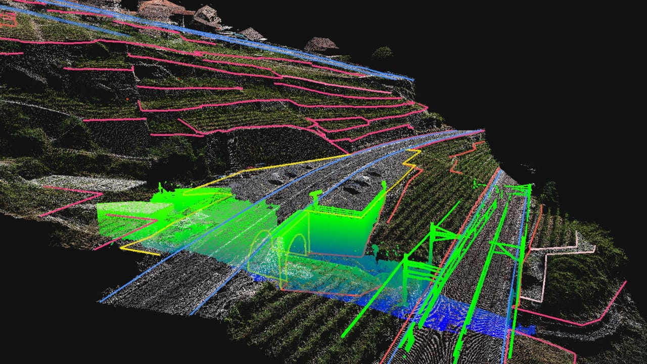
LiDAR, short for Light Detection and Ranging, is an active remote-sensing technology. The sensor emits laser pulses, measures the signal return time, and calculates the distance to the objects or surfaces reached. From millions of measurements, a georeferenced point cloud is generated, representing terrain, vegetation, buildings, structures, slopes, networks, and other surveyed environmental elements.
Because LiDAR does not depend on the visual texture of the surface, it is especially useful where photogrammetry has limitations, such as low-texture areas, unfavorable lighting, partial vegetation cover, or the need for more robust elevation modeling. In airborne surveys, it can also record multiple returns from a single pulse, helping separate vegetation canopy, intermediate objects, and terrain.
The most common platforms include:
- ALS — Airborne Laser Scanning: airborne LiDAR used on aircraft, helicopters, or drones;
- TLS — Terrestrial Laser Scanning: terrestrial scanning commonly used for as-built surveys, buildings, industrial plants, and structures;
- MLS — Mobile Laser Scanning: mobile systems mounted on vehicles, suited to urban corridors, highways, and railways;
- Drone LiDAR: smaller-scale airborne solution useful for specific areas, corridors, slopes, and engineering surveys.
What is photogrammetry?
Photogrammetry is the process of obtaining metric information from images. In drone surveys, for example, photographs are captured with longitudinal and lateral overlap. Specialized software identifies homologous points across images, estimates scene geometry, and generates products such as orthomosaics, digital surface models, point clouds, and textured 3D models.
Photogrammetry’s major advantage is its visual richness. It produces high-resolution imagery useful for interpretation, inspection, stakeholder communication, and construction progress monitoring. When properly planned and supported by adequate field control, it can meet many engineering needs in open areas and visible surfaces.
However, because it depends on imagery, lighting, contrast, and texture, photogrammetry tends to face greater limitations in dense vegetation, homogeneous surfaces, heavily shadowed areas, reflections, water, textureless soil, and elements hidden by vegetation cover.
LiDAR vs photogrammetry: key technical differences
| Criterion | LiDAR | Photogrammetry |
|---|---|---|
| Measurement principle | Active laser-pulse sensor | Geometric reconstruction from overlapping images |
| Typical product | Point cloud, DTM, DSM, profiles, contour lines | Orthomosaic, DSM, textured 3D model, point cloud |
| Lighting dependency | Lower | Higher |
| Visual-texture dependency | Low | High |
| Vegetation | Better ability to estimate terrain under partial cover | Tends to represent the visible top of vegetation |
| Orthophoto | Not the primary product unless combined with a camera | Core product of the methodology |
| Vertical accuracy | Generally more robust when properly controlled and classified | Good in open areas, but sensitive to texture, control, and flight geometry |
| Cost | Usually higher | Usually lower |
| Processing | Requires point-cloud classification, filtering, and quality control | Requires aerial triangulation, calibration, control, and product validation |
| Best application | Terrain, corridors, vegetation, critical elevation work | Imagery, visual inspection, documentation, and exposed surfaces |
Accuracy: the central decision factor
In engineering, accuracy should not be treated as a marketing promise. It must be specified, measured, verified, and reported. This applies to both LiDAR and photogrammetry.
A technically defensible survey should clearly state:
- the adopted geodetic system and vertical datum;
- the field support and control method;
- the number and distribution of control points;
- the number and distribution of independent checkpoints;
- the positional accuracy calculation method;
- whether the reported accuracy is horizontal, vertical, or three-dimensional;
- which products were validated: orthomosaic, DSM, DTM, contours, classified point cloud, or 3D model.
Standards and references such as ASPRS standards for digital geospatial data, Brazilian topographic-survey standards, and geodetic specifications associated with the Brazilian Geodetic System reinforce one essential point: the final product must be validated using objective criteria, not only by the model’s visual appearance.
Where LiDAR stands out
LiDAR tends to be the better choice when a project depends on reliable terrain elevation representation. This is especially important in detailed design, linear infrastructure, drainage, earthworks, transmission lines, railways, highways, network corridors, slopes, and vegetated areas.
1. Terrain beneath vegetation
In vegetated areas, photogrammetry normally reconstructs what the camera can see: tree canopies, shrubs, and visible surfaces. LiDAR, in turn, can record returns at different vegetation levels, increasing the likelihood of identifying points close to natural ground, provided there are sufficient canopy openings and appropriate processing.
2. Linear corridors
Highway, railway, transmission-line, pipeline, fiber-optic, and power-network projects require spatial continuity, elevation control, and the ability to generate longitudinal and cross profiles. In this context, LiDAR is often advantageous because it provides dense point clouds suitable for analyzing interferences, right-of-way, vegetation, obstacles, and terrain geometry.
3. Digital terrain models
When the primary product is a DTM — Digital Terrain Model, LiDAR usually provides greater robustness, especially when the point cloud is properly classified. Separating ground, vegetation, buildings, and other classes is a critical step in turning raw point-cloud data into engineering information.
4. As-built surveys and structural scanning
In industrial plants, substations, buildings, technical rooms, and complex structures, terrestrial laser scanning can capture geometry with high point density. This supports interference analysis, as-built modeling, design-versus-built comparison, and integration with BIM workflows.
To explore this type of digital integration further, see the article on BIM design coordination.
Where photogrammetry stands out
Photogrammetry stands out when visual information is as important as geometric information. In construction, inspections, physical-progress monitoring, documentation of open areas, and orthomosaic generation, it often provides an excellent cost-benefit ratio.
1. High-resolution orthomosaics
The orthomosaic is one of photogrammetry’s strongest products. It allows the surveyed area to be viewed in rich detail, visible surface elements to be identified, occupations to be checked, visible interferences to be mapped, and field status to be communicated to technical teams and managers.
2. Visual construction documentation
For execution monitoring, time-based comparison, progress records, and client communication, photogrammetry provides an intuitive product. Imagery makes interpretation easier for non-specialist teams, without eliminating the need for technical control when metric use is intended.
3. Open areas and well-textured surfaces
On terrain with good visibility, low vegetation, adequate lighting, and sufficient texture, photogrammetry can generate highly useful engineering models, provided flight planning, overlap, GSD, and control points are properly specified.
4. Cost-benefit in lower-complexity scopes
When the objective is visual mapping, inspection, orthophotos, or modeling of exposed surfaces, photogrammetry tends to cost less than LiDAR. This does not mean it is “inferior”; it means it responds better to certain objectives.
DTM, DSM, and point clouds: concepts that should not be confused
A common procurement error is to confuse different geospatial products. Three terms require particular attention:
- Point cloud: a set of georeferenced three-dimensional points representing surfaces, objects, or terrain;
- DSM — Digital Surface Model: represents the visible surface, including buildings, vegetation, and objects;
- DTM — Digital Terrain Model: represents natural terrain or ground after filtering or classifying above-ground elements.
In photogrammetry, the initially generated model commonly approximates a DSM because it derives from what the camera can observe. In LiDAR, the ability to classify returns increases the capability to generate a DTM, but this is not automatic: it depends on density, acquisition quality, processing, classification, and validation.
How to choose between LiDAR and photogrammetry
The decision should begin with the required final product, not with the available equipment. Below is a practical decision matrix.
| Project scenario | Most suitable technology | Technical reason |
|---|---|---|
| Vegetated area requiring terrain data | LiDAR | Greater ability to estimate terrain under partial cover |
| Orthomosaic for visual documentation | Photogrammetry | High-resolution visual product |
| Transmission-line, railway, or highway corridor | LiDAR or hybrid solution | Requires profiles, terrain, obstacles, and spatial continuity |
| Visual construction monitoring | Photogrammetry | Good visual communication and lower recurring cost |
| As-built survey of an industrial installation | Terrestrial laser scanning | High geometric density in the built environment |
| Project requiring a reliable DTM | LiDAR | Better basis for ground classification and elevation analysis |
| Urban area requiring both visual and metric information | Hybrid solution | Combines LiDAR geometry with image texture |
| Low-cost preliminary survey | Photogrammetry | Good cost-benefit when required accuracy allows |
When to combine LiDAR and photogrammetry
In many projects, the best answer is not to choose one technology and exclude the other. Combining LiDAR and photogrammetry can provide a more complete product: LiDAR contributes geometry and elevation information; photogrammetry contributes texture, orthophotos, and visual interpretation.
This hybrid approach is especially useful for:
- modeling cities, industrial plants, and complex infrastructure;
- projects requiring both a DTM and an orthophoto;
- surveys for BIM, digital twins, and as-built documentation;
- areas combining vegetation, buildings, and exposed surfaces within the same scope;
- interference studies in infrastructure corridors.
In multidisciplinary projects, integration between surveying, design, and information management should be planned from the outset. This is similar to the care applied in basic-design checklists before construction procurement.
Criteria for specifying the survey in a contract
A common mistake is to procure a “drone survey,” “LiDAR survey,” or “photogrammetry” without technically specifying the expected products. This creates room for visually impressive deliverables that are still insufficient for engineering purposes.
An adequate specification should define, at minimum:
- technical objective: preliminary study, conceptual design, basic design, detailed design, as-built, inspection, or documentation;
- final product: orthomosaic, DTM, DSM, classified point cloud, contour lines, profiles, cross-sections, 3D model, accuracy report;
- reference system: datum, projection, vertical datum, and integration with the Brazilian Geodetic System where applicable;
- required accuracy: horizontal, vertical and, when necessary, three-dimensional;
- field control: control points, independent checkpoints, and GNSS/topographic method;
- density or resolution: LiDAR point density, photogrammetric GSD, and minimum criteria by area;
- classification: required point-cloud classes, such as ground, vegetation, buildings, structures, and noise;
- digital deliverables: formats, metadata, technical memorandum, processing report, and validation report;
- acceptance criteria: how the client will verify whether the deliverable meets the scope.
This level of detail reduces contractual disputes and improves the technical traceability of decisions. It also brings the survey closer to an Owner’s Engineering and engineering consulting approach, in which the client needs evidence to decide, audit, and approve deliverables.
Common mistakes when procuring LiDAR or photogrammetry
1. Confusing attractive imagery with reliable data
A sharp orthomosaic or visually attractive 3D model does not, by itself, guarantee metric accuracy. Visual quality helps interpretation, but technical reliability depends on control, calibration, processing, and validation.
2. Not requiring an accuracy report
Without an accuracy report, the client has no objective basis for determining whether the survey meets project requirements. Accuracy should be demonstrated with independent checkpoints and a declared methodology.
3. Failing to distinguish DTM from DSM
For earthworks, drainage, and detailed design, using a DSM as if it were a DTM can create significant errors, especially in areas with vegetation or above-ground objects.
4. Procuring technology without defining the final use
The survey should be specified based on its final use. A product intended for visual inspection does not necessarily serve detailed design. A detailed-design product requires stricter control and validation requirements.
5. Ignoring integration with BIM and other disciplines
When the survey will be used for BIM modeling, coordination, or construction planning, formats, information requirements, coordinate systems, and integration responsibilities must be defined.
Conclusion: LiDAR and photogrammetry are complementary
LiDAR and photogrammetry should not be treated as competing solutions in every scenario. Each technology has its own advantages, limitations, and preferred applications. LiDAR stands out when the priority is geometry, elevation, terrain, vegetation, and robust point-cloud data. Photogrammetry stands out when the priority is orthophotos, texture, visual inspection, documentation, and cost-benefit in open areas.
For engineering projects, the decision should be guided by accuracy, final product, field conditions, project risks, and acceptance criteria. In many cases, the best solution will be hybrid, combining LiDAR’s geometric precision with photogrammetry’s visual richness.
A3A Engenharia supports clients, designers, and technical managers in specifying, analyzing, and validating geospatial surveys for infrastructure, energy, telecommunications, construction, and BIM integration.
Frequently asked questions about LiDAR vs photogrammetry
Is LiDAR more accurate than photogrammetry?
Not necessarily in every case. LiDAR tends to be more robust for elevation and terrain, especially in vegetation, but accuracy depends on the sensor, platform, field control, processing, and validation. Photogrammetry can also achieve strong results in open, well-controlled areas.
Does drone photogrammetry replace a topographic survey?
It depends on the scope. For visual documentation and mapping visible surfaces, it may be sufficient. For detailed design, setting out, earthworks, or drainage, accuracy, control, checkpoints, and compatibility with applicable standards must be specified.
When should LiDAR be used instead of photogrammetry?
Use LiDAR when the project requires better terrain representation, surveying in vegetated areas, rigorous elevation analysis, linear corridors, dense point clouds, or integration with three-dimensional engineering models.
When is photogrammetry sufficient?
Photogrammetry tends to be sufficient when the area is open, well lit, has good visual texture and low vegetation, and when the primary product is an orthomosaic, visual documentation, inspection, or a 3D model of visible surfaces.
What is the difference between DTM and DSM?
A DSM represents the visible surface, including vegetation, buildings, and objects. A DTM represents the terrain, normally after filtering or classifying above-ground elements. For engineering, this distinction is critical.
Can LiDAR and photogrammetry be combined?
Yes. The combination is often recommended when a project needs both geometry and elevation information as well as orthophotos and visual texture. This hybrid solution can reduce uncertainty and improve technical interpretation.
Technical references consulted
- ASPRS. Positional Accuracy Standards for Digital Geospatial Data, Edition 2, Version 2, 2024.
- NOAA Coastal Services Center. LiDAR 101: An Introduction to LiDAR Technology, Data, and Applications, 2012.
- DNIT. ISF-202: Levantamento Aerofotogramétrico e Perfilamento a Laser para Projetos Executivos de Ferrovias, 2015.
- IBGE. Especificações e Normas para Levantamentos Geodésicos associados ao Sistema Geodésico Brasileiro, 2017.
- ABNT. NBR 13133 — Execução de Levantamento Topográfico — Procedimento.
- Internal A3A/ENGiOS references on LiDAR, photogrammetry, laser scanning, drone surveying, GNSS, and BIM.
