
Understand EMC and EMI in engineering: coupling paths, shielding, grounding, structured cabling, fiber, surge protection, diagnosis, and mitigation.
Check it out!
Electromagnetic compatibility (EMC) is the ability of equipment and systems to operate correctly in the same environment without producing intolerable disturbances or suffering unacceptable degradation caused by electromagnetic phenomena. In engineering, this requires simultaneously addressing emissions, immunity, coupling paths, grounding/equipotential bonding, shielding, routing, surge protection and the interfaces among power, telecommunications, automation, and electronic systems.
Electromagnetic interference (EMI) is the unwanted effect: noise, communication failure, packet loss, resets, incorrect readings, spurious alarms, degraded images, improper I/O actuation, or recurring damage to interfaces. Correct diagnosis avoids repeatedly replacing equipment without eliminating the systemic cause.
EMC and EMI: practical difference for engineering projects
EMC describes a desired condition of coexistence. EMI describes a disturbance that actually degrades performance. A variable frequency drive, switching power supply, or radio transmitter may emit electromagnetic energy without necessarily causing failures. The issue becomes interference when that energy reaches a susceptible circuit at an intensity and frequency capable of altering its operation.
The analysis should always identify three elements: source, coupling path and affected system. Mitigation can act on any of them. Sometimes reducing emissions at the source is most effective; in other cases, changing routing, improving equipotential bonding, using fiber optics, or increasing interface immunity is technically superior.
Conducted and radiated emissions
Emissions conducted propagate through power conductors, signal cables, shields, protective conductors, functional references, or metallic structures. They may appear in differential mode, between conductors of the same circuit, or in common mode, when the conductor set shifts in potential relative to the equipotential reference.
Emissions radiated propagate through space via electric, magnetic, or electromagnetic fields. Cables, panel openings, PCB traces, metallic structures, and even grounding connections can behave as antennas when their dimensions and geometry are relevant to the frequencies involved.
In practice, both forms can coexist. A switching transient may leave equipment through the power supply, circulate through a metallic structure, and radiate into a nearby signal circuit. Therefore, classifying the issue merely as “cable noise” is usually insufficient.
Immunity and susceptibility
Immunity represents the ability of equipment to maintain performance under a given disturbance. Susceptibility is the tendency to degrade when exposed to it. Individual product compliance with an EMC standard is important, but does not guarantee the performance of the installed system.
The real environment may include longer cable lengths, routes near power circuits, interfaces absent from type testing, poor grounding, potential differences, equipment from different manufacturers, and combinations of disturbance sources. Installation engineering must ensure that the overall system remains within compatible conditions.
Main EMI sources in buildings and industrial plants
The most common sources include:
- variable frequency drives and electronic drives;
- motors, contactors, relays, and solenoids;
- transformers, busbars, and high-current feeders;
- UPS systems, rectifiers, switching power supplies, and chargers;
- welding machines, furnaces, and highly variable loads;
- capacitor banks and electrical switching;
- transmitters, antennas, and radio-frequency systems;
- electrostatic discharges;
- lightning and conducted or induced surges;
- poor shielding and equipotential bonding connections.
Severity does not depend only on source power. Distance, frequency, parallel run length, loop area, connection impedance, shielding, transient rise time, and immunity of the affected equipment can be decisive.
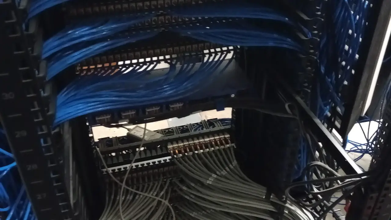
A3A Engenharia archive — real rack and cabling infrastructure in a mission-critical environment.
How interference couples into circuits
Conducted coupling
It occurs when the disturbance uses a common metallic connection. Noise may circulate through power conductors, signal references, protective conductors, or shields. Potential differences between interconnected equipment may also generate currents through communication interfaces.
In metallic links between buildings or areas with different electrical references, this mechanism needs to be evaluated before attributing the failure to the protocol or cable category. In many cases, a transition to fiber optics eliminates the galvanic path and dramatically reduces risk.
Capacitive coupling
Capacitive coupling results from the electric field between nearby conductors or surfaces. It increases with voltage, frequency, capacitance, and parallel length. Separation, reduced parallelism, shielding, and control of electrical references help reduce this mechanism.
Inductive coupling
Inductive coupling results from variations in the magnetic field. High currents and rapid current changes induce voltages in nearby loops. Receiver loop area is critical: twisted pairs reduce this effective area and improve rejection, but they do not make the circuit immune to every environment.
Radiated coupling
At higher frequencies, cables, structures, and openings can capture or radiate energy similarly to antennas. The effectiveness of enclosures and shields then depends on electrical continuity, opening size, connection length, and high-frequency impedance.
EMC in structured cabling
Communication problems are not always switch or protocol failures. When the cause involves routing, shielding, equipotential bonding, or interference, diagnosis needs to treat the physical infrastructure as a system.
Balanced twisted-pair cabling was designed to reject common-mode noise and limit crosstalk. However, its performance depends on the complete system: cable, connectors, patch cords, patch panels, racks, terminations, physical organization, and installation quality.
EMC problems may manifest as retransmissions, errors, packet loss, and instability. Before concluding that external interference exists, internal link causes should also be checked: excessive length, incompatible category, excessive untwisting, poor termination, bend radius, bundle compression, shield continuity, and certification results.
The decision among U/UTP, F/UTP, U/FTP, S/FTP, or fiber should be based on the environment and risk, not on the idea that “more shielding is always better.” In controlled corporate environments, U/UTP may be sufficient. In industrial installations, high-density environments, proximity to power, or locations with relevant disturbances, shielded or optical solutions may be more appropriate.
Shielding: what it does and what it does not do
Shielding reduces the electromagnetic energy that reaches internal conductors and provides a controlled path for induced currents. Its effectiveness depends on material, coverage, frequency, continuity, geometry, and termination method.
Shielding does not automatically correct:
- poor routing near strong sources;
- potential differences between systems;
- lack of equipotential bonding;
- incompatible connectors;
- loss of shield continuity;
- poor termination;
- surge or lightning problems;
- a link that already fails electrical certification.
Terminology also needs to be precise. Generic terms such as “FTP” or “STP” can hide different constructions. In design, it is preferable to specify constructions such as F/UTP, U/FTP, and S/FTP, making clear where overall shielding exists and where pair shielding exists.
Grounding and equipotential bonding in EMC
Equipotential bonding reduces potential differences and provides coherent references among racks, panels, structures, and systems. For high-frequency phenomena, connection geometry and impedance may be more relevant than resistance measured at DC.
ABNT NBR 17040 addresses equipotential bonding of telecommunications infrastructure and reinforces the need for a coherent architecture for racks, bonding bars, and shields. The design should integrate telecommunications infrastructure with the building’s equipotential bonding system, without creating improvised “isolated grounds.”
There is no universal “ground at one end” or “ground at both ends” rule applicable to every cable and frequency. The decision depends on architecture, potential differences, interference mechanism, manufacturer instructions, and the equipotential bonding system.
The shield itself also must not be used as an equipotential bonding conductor for racks or cabinets. These are distinct functions: the equipotential bonding system should have its own bars, conductors, and connections.
Segregation between power and signal
Physical separation between power and telecommunications circuits reduces coupling, but there is no single fixed distance valid for every situation. The criterion depends on power, current, voltage, frequency, parallel length, metallic infrastructure, shielding, and applicable standards.
Good practices include:
- use separate compartments or routes when necessary;
- minimize parallel runs near high-current feeders;
- cross circuits, when necessary, at close to 90°;
- reduce loop areas;
- maintain proper continuity of metallic infrastructure when it forms part of the EMC strategy;
- coordinate power, telecom, automation, and security routes during design.
When fiber optics is the better solution
Fiber optics is immune to electromagnetic coupling in the transmission medium and eliminates the galvanic path between connected equipment. It may therefore be the best solution for backbones between buildings, industrial areas, substations, outdoor yards, routes near power systems, or locations subject to large potential differences.
This does not mean that every camera, sensor, or device should be connected directly by fiber. In many projects, an efficient architecture combines fiber in the backbone with copper for local access, reducing electromagnetic exposure without losing the practicality of PoE at the edge.
Surges, lightning, and NBR 5419-4
ABNT NBR 5419-4:2026 addresses protection of internal electrical and electronic systems against lightning effects. It uses concepts such as Lightning Protection Zones (LPZ) and combines protection measures:
- equipotential bonding;
- spatial shielding;
- line routing and shielding;
- isolating interfaces;
- coordinated surge protective device systems.
SPDs limit conducted surges, but do not by themselves eliminate radiated fields or inductive coupling. Systems with power and communication ports need a coordinated strategy: protecting only the power supply can leave an entry path open through the signal line.
Relationship between EMC and power quality
Power quality and EMC overlap, but they are not synonymous. Sags, swells, interruptions, harmonics, and imbalances are normally analyzed through the power supply. EMC also covers noise on signal lines, common-mode disturbances, radiated fields, ESD, fast transients, and coupling between systems.
A failure that always occurs when a large motor starts may correlate with power quality; a failure that appears only on an Ethernet interface near a drive may require investigation of common mode, grounding, shielding, and routing. In both cases, measuring without an engineering hypothesis tends to generate large amounts of data and few conclusions.
EMI diagnosis: an evidence-based method
Intermittent failures require correlation among symptoms, electrical events, routes, and measurements. The correct approach avoids successive equipment replacements without eliminating the cause.
A consistent diagnosis should build and test hypotheses. A recommended sequence is:
- record symptoms, times, affected devices, and operating conditions;
- identify recent changes, starts, switching events, or nearby sources;
- review diagrams, routes, interfaces, grounding, and shields;
- correlate failures with network, automation, and power-quality logs;
- measure at points capable of separating source, propagation, and impact;
- perform controlled tests when safe;
- implement corrections in stages;
- validate whether the symptom was actually eliminated.
Measurements may involve voltage, current, spectrum, potential difference, shield current, common-mode signals, network analyzers, or simultaneous records at different points. The instrument should have a frequency range, resolution, and installation method compatible with the phenomenon under investigation.
Typical symptoms that justify EMC investigation
Some symptoms deserve attention when they persist even after functional equipment checks:
- communication interfaces that lose link without a clear cause;
- cameras that reset or freeze at certain times;
- PLCs that record sporadic I/O faults;
- sensors with inconsistent readings near machine starts;
- switches with high physical-layer error counts on specific ports;
- spurious alarms with no corresponding process event;
- recurring damage to communication ports;
- instability that disappears when nearby equipment is turned off.
These symptoms do not prove EMI, but they help build hypotheses and define where to measure.
Mitigation: correct the cause, not only the symptom
Measures should correspond to the identified mechanism. Alternatives include:
- reduce emissions at the source;
- apply filters, ferrites, reactors, or isolating interfaces;
- review routing and segregation;
- reduce loop areas;
- correct shields and terminations;
- improve equipotential bonding;
- coordinate SPDs on power and signal circuits;
- use fiber optics to interrupt metallic paths;
- replace unsuitable interfaces with higher-immunity versions;
- review functional grounding and protective grounding topology.
Applying solutions by trial and error can shift the problem or mask the symptom. An unsuitable filter may saturate; a poorly terminated shield may be ineffective; a new cable may improve electrical margin without resolving the surge path damaging the ports.
EMC in IP video surveillance, access control, and critical networks
Electronic security systems combine distributed devices, PoE, facades, rooftops, parking areas, racks, and external interfaces. This creates a combination of EMI, surge, and potential-difference risks.
For outdoor cameras, shielding may be only one part of the strategy. Depending on the environment, the design may require signal SPDs, coordination with the lightning protection system, suitable enclosures, equipotential bonding, transition to fiber, or topology changes. In access control, doors and readers near motors, turnstiles, and electromagnets also require analysis of switching and return currents.
EMC in industrial environments
In industrial facilities, the electromagnetic environment is usually more severe. MICE classification, segregation between automation and power, selection of industrial cables, fiber architecture, and technical-room design need to be addressed from the design stage.
Indiscriminate use of shielded cable does not replace a compatibility design. Often, the most robust solution is to relocate the route, reduce parallel runs with power, bring fiber to a local area, and keep copper only where necessary.
EMC in Data Centers and technical rooms
Data Centers concentrate UPS systems, PDUs, switching power supplies, racks, high-density cabling, and multiple systems. The concern is not only “noise,” but also availability, signal integrity, and behavior during surge or electrical-failure events.
Coordination between power and telecommunications should be addressed in layout, routing, equipotential bonding, and documentation. Improvised changes to racks and pathways can degrade an originally adequate EMC strategy.
Product testing vs. installation diagnosis
Formal emission and immunity tests performed in laboratories verify products according to specific methods and limits. Field diagnosis is different: it investigates the behavior of a real installation, its coupling paths, and its symptoms.
A field report may document sources, measurements, hypotheses, actions, and results, but it should not be presented as laboratory product-compliance certification when those tests were not performed.
Deliverables of a field EMC analysis
Depending on scope, a technical analysis may produce:
- map of sources and sensitive systems;
- record of symptoms and correlated events;
- survey of routes, racks, and equipotential points;
- reference and confirmation measurements;
- coupling-path analysis;
- prioritized mitigation plan;
- recommendations for shielding, segregation, or fiber;
- grounding/equipotential bonding guidelines;
- post-correction verification;
- technical report with evidence and traceability.
Diagnostic matrix: how to distinguish physical defects, EMI, and power problems
An efficient EMC investigation must avoid diagnosis by association. The fact that a failure occurs near a motor, drive, or electrical panel does not prove electromagnetic interference; likewise, a link that shows link up does not prove that the physical layer is healthy. The safest method is to separate competing hypotheses and seek evidence capable of eliminating alternatives.
In Ethernet networks, for example, the first set of checks should confirm category, length, termination, certification parameters, and port statistics. CRC errors, link flaps, retransmissions, or packet loss may result from physical defects, transceivers, configuration, congestion, or EMI. If symptoms appear only when a particular machine enters operation, temporal correlation strengthens the electromagnetic hypothesis, but it still needs to be tested against measurements.
| Symptom | Hypotheses to Verify | Useful Evidence |
|---|---|---|
| Ethernet link drops during machine start | EMI, voltage sag, PoE supply, termination, transceiver | switch logs, waveform, certification, temporal correlation |
| Electronic ports fail repeatedly | surges, potential differences, insufficient protection, external routing | grounding topology, SPDs, lightning protection, route inspection |
| Sensor shows unstable readings | inductive/capacitive coupling, reference, grounding, sensor defect | oscillography, route comparison, controlled source shutdown |
| Camera freezes but remains powered | network, firmware, EMI, PoE, server/VMS | ping, port errors, logs, cross-testing, and traffic capture |
This approach avoids one of the most common field failures: changing cable, grounding, equipment, and configuration simultaneously. When several variables are changed at once, even a real improvement does not demonstrate which intervention solved the problem. Diagnosis should preserve traceability among hypothesis, test, change, and result.
EMC in design, procurement, and construction inspection
Electromagnetic compatibility also needs to appear in engineering documents. A design that merely states “use shielded cable where interference exists” transfers to construction a decision that should have been studied earlier. The specification should identify environments, interfaces, segregation criteria, media type, equipotential bonding requirements, surge protection, and responsibilities of each discipline.
In procurement, technical equivalence cannot be assessed only by category, rated voltage, or presence of shielding. Cables, connectors, filters, SPDs, and interfaces have parameters that must be compared with the functional requirement. Replacing a component may change impedance, shielding coverage, frequency range, surge capability, rated current, or installation method. The approval process should record these differences before purchase.
During construction inspection, attention shifts to the as-built condition. Routes may be altered to bypass physical obstacles, cable trays may lose continuity, signal cables may share spaces not foreseen in design, and equipotential bonding conductors may be omitted. Photographs, inspections, daily reports, nonconformance records, and As-Built updates form the evidence trail needed to demonstrate that the design’s EMC strategy was preserved.
- verify critical routes before ceilings and shafts are closed;
- confirm continuity and connections of specified metallic elements;
- inspect shield terminations and connectors;
- record relevant crossings and parallel runs with power circuits;
- validate integration of racks and bonding bars into the equipotential system;
- confirm SPDs and interfaces at specified boundaries;
- update drawings when an authorized change occurs.
For the owner, this discipline reduces the risk of receiving an installation that appears to work during commissioning but exhibits intermittent failures when the plant reaches full operating conditions.
Example investigation of a network subject to interference
Consider an industrial area where IP cameras and controllers lose communication during motor starts. The first action should not be to replace all cabling with a shielded version. The investigation begins by identifying which points fail, which remain stable, which routes are common, and which electrical event coincides with the symptom.
If only links routed through the same cable tray show errors, the route becomes a relevant variable. If all devices on one switch reset simultaneously, power and PoE should also be evaluated. If communication fails without a reset and physical port counters increase during startup, the hypothesis of a disturbance in the medium becomes stronger. If the problem disappears when a section is temporarily replaced with fiber, additional evidence is obtained about the metallic path.
The final solution may involve a combination of measures: route changes, reduced parallelism with power circuits, fiber in the backbone, correction of equipotential bonding, replacement of connectivity, surge protection, or adjustment of the disturbance source itself. The value of diagnosis lies precisely in avoiding the automatic prescription of a single technology.
Final considerations
Electromagnetic compatibility is not achieved through a single solution. It results from coordination among source, coupling path, immunity, cabling, power, grounding, shielding, surge protection, and physical architecture.
In many cases, the cost of correcting EMI after implementation is much higher than addressing it during design. Reserving suitable routes, specifying fiber at the right points, coordinating equipotential bonding, and providing interface protection help prevent intermittent failures and recurring equipment replacement.
For existing installations, diagnosis should be evidence-based. The cause needs to be demonstrated before permanent correction; otherwise, the intervention may merely move the symptom elsewhere.
Electromagnetic compatibility should be resolved through systems engineering: source, path, victim, protection, equipotential bonding, and validation. In critical installations, prevention during design reduces operational risk and retrofit cost.
Technical references
[1] BRAZILIAN ASSOCIATION OF TECHNICAL STANDARDS. ABNT NBR 5410:2004 — Low-voltage electrical installations. Available at: https://www.abntcatalogo.com.br/
[2] BRAZILIAN ASSOCIATION OF TECHNICAL STANDARDS. ABNT NBR 5419-4:2026 — Lightning protection — Electrical and electronic systems within structures. Available at: https://www.abntcatalogo.com.br/
[3] BRAZILIAN ASSOCIATION OF TECHNICAL STANDARDS. ABNT NBR 17040 — Equipotential bonding of telecommunications infrastructure. Available at: https://www.abntcatalogo.com.br/
[4] INTERNATIONAL ELECTROTECHNICAL COMMISSION. IEC 61000 — Electromagnetic compatibility (EMC) series. Available at: https://www.iec.ch/
[5] INTERNATIONAL ORGANIZATION FOR STANDARDIZATION; INTERNATIONAL ELECTROTECHNICAL COMMISSION. ISO/IEC 11801 — Information technology — Generic cabling for customer premises. Available at: https://www.iso.org/
Frequently asked questions
EMC is the compatibility condition in which systems coexist without causing or suffering incompatible disturbances. EMI is interference that reaches a circuit and degrades its operation.
No. Effectiveness depends on cable construction, shield continuity, connectors, terminations, equipotential bonding, frequency, routing, and installation quality.
No. Grounding and equipotential bonding help control potentials and current paths, but correction also depends on the source, frequency, coupling, shielding, and immunity.
It may be the best solution when the problem is the metallic path between areas because fiber is immune to electromagnetic coupling in the transmission medium and eliminates the galvanic connection.
No. SPDs limit conducted surges. Radiated fields, coupling, common-mode noise, and routing problems may require other measures.
Diagnosis correlates symptoms and operating conditions, identifies sources and paths, reviews routes and equipotential bonding, measures at the right points, and validates each correction.
It addresses equipotential bonding of telecommunications infrastructure, an essential aspect of integrating racks, bonding bars, shields, and references coherently.
No. A field report documents the installation and diagnostic measures; formal product tests follow specific methods and limits in a controlled environment.
