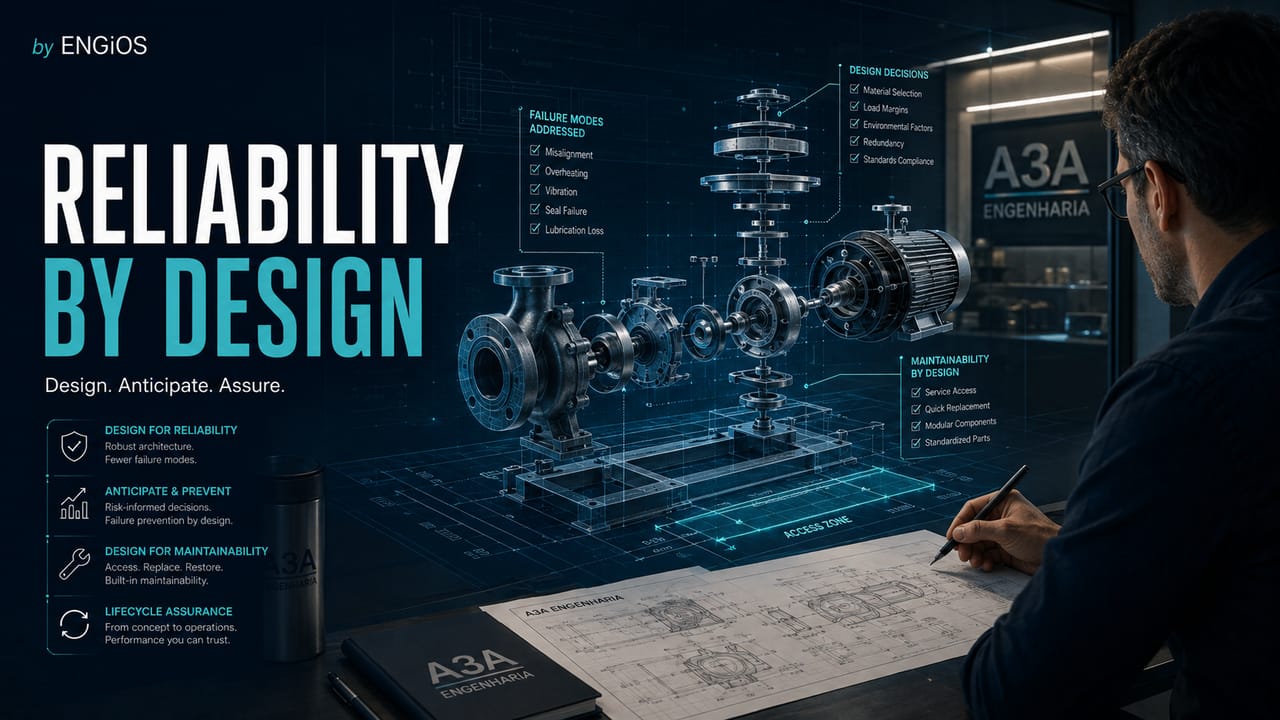
Reliability by Design applied to engineering systems: requirements, architecture, redundancy, common cause, maintainability, testability, FMEA, Design Review, and verification.
Check it out!
Reliability by Design is the systematic application of engineering requirements, analyses, and decisions so that reliability, availability, maintainability, and support are not evaluated only after the system enters operation. The logic is simple: dependability characteristics are strongly determined during requirements definition, architecture, specification, component selection, interfaces, accessibility, redundancy, protection, testing, and preparation for maintenance.
When these attributes are addressed late in the project, the organization tends to compensate for design limitations with inventory, excessive inspections, operational contingencies, difficult interventions, or redundancies added afterward. The result may be technically functional at delivery, but expensive, fragile, or difficult to sustain throughout the lifecycle.
Designing for reliability does not mean pursuing zero failures or adding redundancy indiscriminately. It means transforming service needs and failure consequences into verifiable requirements and making conscious decisions about architecture, components, margins, maintainability, diagnostics, support, and performance evidence.
What Is Reliability by Design?
Reliability by Design, often associated with Design for Reliability — DfR, is an engineering approach in which dependability attributes are treated as design requirements from the earliest phases. IEC 60300-1:2024 structures dependability as the ability of a system, product, or service to perform as required when required, considering the lifecycle and the interfaces among technical, financial, and management aspects.
In practice, Reliability by Design connects four questions:
- what function the system must perform and under which conditions;
- for how long, or at what availability level, that function must remain accessible;
- how the system can fail and which consequences are acceptable;
- how to detect, isolate, repair, recover, and sustain the system when degradation or failure occurs.
The answer does not belong to a single discipline. Electrical, automation, telecommunications, mechanical, civil, software, operations, maintenance, security, and supply chain may all contribute to the dependability of the same system.
Reliability Requirements Must Come Before the Solution
A common mistake is to define the architecture first and only then ask what reliability it provides. A more robust path reverses the logic: define the service need, establish criteria, and only then select an architecture capable of meeting them.
IEC 60300-3-4:2022 provides guidance for specifying quantitative and qualitative requirements for reliability, maintainability, supportability, and availability. This helps distinguish vague targets from verifiable requirements.
“Highly reliable system” is not a technical requirement. Better formulations may include:
- minimum operational availability for a defined period;
- probability of success during a mission;
- maximum restoration time for a given failure class;
- single-failure tolerance for critical functions;
- limit on capacity loss under degraded conditions;
- need for automatic testing, diagnostics, or failure indication;
- accessibility and replacement time for critical modules.
The requirement must include the operational context. Temperature, dust, humidity, vibration, load regime, switching, cycles, power quality, traffic profile, environmental aggressiveness, and maintenance team capability all affect expected performance.
Reliability must be specified before it can be verified. Vague requirements such as “high availability” do not guide architecture, testing, or technical acceptance.
Required Function and Functional Failure
Reliability must be associated with the required function, not only with the component. A piece of equipment may be energized and apparently intact while the system has already lost the required function.
Consider a power supply system for a critical load. The function may be to provide power within voltage and frequency limits, with continuity compatible with the process. A functional failure may be total loss, but it can also be transfer beyond the allowed time, insufficient autonomy, or degraded operation without capacity to withstand an additional contingency.
This formulation brings Reliability by Design closer to FMEA, FMECA, RCM, and RAM analysis. The architecture is studied in relation to functions and consequences, not merely equipment lists.
Architecture: Series, Parallel, and Redundancy
Architecture is one of the decisions with the greatest impact on system reliability. In a purely series chain, failure of any required element can interrupt the function. In parallel, redundant, or reconfigurable architectures, the function can be preserved even after certain failures.
In a simplified model with independent components and reliabilities R1, R2, and R3 in series:
Rs = R1 × R2 × R3
If each element has a reliability of 0.98 over the interval analyzed, chain reliability will be approximately 0.941. The presence of several good elements does not guarantee that the system is equally good.
For two independent elements in parallel, when only one needs to operate:
Rp = 1 − (1 − R1)(1 − R2)
With two elements rated at 0.98, the theoretical value increases to approximately 0.9996. This result, however, is only realistic if the independence assumptions are plausible.
Redundancy Does Not Eliminate Common-Cause Failures
Two identical pieces of equipment may share the same power supply, room, software, firmware, sensor, control logic, network, operating procedure, or design error. In these cases, physical redundancy does not represent complete functional independence.
Common-cause failures need to be considered in layout and architecture. Examples include:
- two redundant switches powered by the same circuit;
- two controllers depending on a single sensor;
- two pumps in parallel with a common suction line susceptible to blockage;
- redundant equipment installed in the same flood-prone environment;
- two communication routes sharing the same physical infrastructure;
- redundant UPS systems depending on the same bypass element.
The design question is not “how many pieces of equipment are there?”, but how many truly independent paths exist to the required function.
Apparent redundancy can hide single points of failure. The analysis must consider dependencies, common causes, and the real ability to maintain the function under degraded conditions.
Maintainability Must Be Designed
IEC 60300-3-10:2025 reinforces the relationship among maintainability, maintenance, and other dependability attributes throughout the lifecycle. A large portion of restoration time is influenced by physical and informational design decisions.
Maintainability involves, among other factors:
- safe access to components;
- space for removal and replacement;
- modularity;
- standardization of interfaces;
- test and measurement points;
- identification and labeling;
- energy isolation and sectionalizing;
- the possibility of performing maintenance without interrupting adjacent functions;
- ease of diagnosis;
- availability of procedures and data;
- need for special tools.
A valve installed without maintenance clearance, a panel whose intervention requires shutting down multiple loads, or a critical module buried in an architecture without diagnostics are examples of maintainability debt created during design.
Testability and Diagnostics
Diagnostics are part of Reliability by Design because they reduce the time between the manifestation of a failure and identification of the element that requires intervention.
A well-designed system should answer, according to criticality, questions such as:
- is the failure automatically detectable;
- is there an unambiguous indication of the degraded state;
- can the failure be located at the appropriate intervention level;
- are there safe measurement points;
- do alarms distinguish cause from effect;
- do logs preserve relevant events;
- can the team test the protection or redundancy function without creating unnecessary risk.
In digital systems, observability, time synchronization, logs, alarms, internal diagnostics, and telemetry directly influence the speed and quality of recovery.
FMEA and FMECA During Design
IEC 60812:2018 structures FMEA and FMECA as methods for identifying how items or processes can fail, their effects, and the required treatments. During design, these analyses are especially valuable because there is still freedom to change the architecture.
A useful sequence is:
- Define the function and requirement.
- Identify the functional failure.
- Identify plausible failure modes.
- Assess local and system-level effects.
- Identify causes and mechanisms.
- Verify existing controls.
- Assess criticality.
- Define a design, control, or verification action.
- Record evidence of closure.
The action may result in a component change, additional protection, technological diversity, physical separation, improved access, diagnostics, logic changes, or simply validation that residual risk is acceptable.
Design Review With a Reliability Focus
Design Review should not be limited to checking graphical consistency, clashes, or scope compliance. IEC 61160 treats design review as a mechanism for verifying input requirements and stimulating design improvement.
A dependability-oriented review may assess:
| Dimension | Review questions |
| Function | are service requirements measurable? |
| Architecture | are there critical single points of failure? |
| Redundancy | are redundant paths truly independent? |
| Protection | are failures contained or propagated? |
| Maintainability | is intervention safe, accessible, and executable? |
| Testability | can protections and redundancies be verified? |
| Support | are spare parts, tools, and competencies viable? |
| Data | what evidence will be collected during operation? |
| Lifecycle | have obsolescence and renewal been considered? |
The review is most effective when it occurs before the solution is frozen. Finding a single point of failure in a conceptual architecture costs far less than finding it during commissioning or operation.
Derating, Margins, and Component Stress
Reliability by Design also addresses the relationship between stress and capacity. Components operating continuously near thermal, electrical, or mechanical limits may exhibit degradation behavior different from that considered under nominal conditions.
Design practices may include appropriate margins, thermal management, loading analysis, power quality, surge protection, vibration control, environmental selection, and transient verification.
This does not mean indiscriminate oversizing. Excessive margins can also increase CAPEX, space, mass, losses, or complexity. The decision should relate actual service conditions, criticality, failure behavior, and lifecycle cost.
Reliability Growth and Accelerated Testing
New projects may require evidence before years of field data have accumulated. IEC 62506:2023 presents accelerated test methods for identifying design weaknesses and obtaining reliability information within compressed periods.
The principle is different from simply “testing harder.” The test must represent relevant failure mechanisms and have a technically defensible relationship with the mission profile or use environment.
Reliability growth occurs when failures and weaknesses identified during development, testing, or operation feed corrective design actions. Testing without closing causes and actions merely produces a defect list; the reliability gain comes from the cycle detect → analyze → correct → verify.
Reliability and Software
Modern systems combine hardware, software, networks, data, and logic. Dependability cannot be assessed only through physical failure rates.
For software and automation, important decisions include:
- handling invalid states;
- watchdogs and recovery mechanisms;
- segregation of critical functions;
- configuration management;
- versioning and rollback;
- tolerance to communication loss;
- restart behavior;
- data consistency;
- exception handling;
- integration testing and degraded scenarios.
An architecture with redundant hardware may remain vulnerable if both instances run the same defective logic or depend on the same incorrect configuration.
Support, Spare Parts, and Obsolescence During Design
Reliability as perceived by the user also depends on the ability to restore service. A rare, proprietary, or long-lead-time component can turn a technically simple failure into prolonged unavailability.
During design, it is worth assessing:
- criticality of spare parts;
- replacement lead time;
- standardization across systems;
- possibility of equivalent substitution;
- commercial life of the product;
- dependence on licenses, firmware, or external services;
- documentation required for future maintenance.
These factors connect Reliability by Design to Life Cycle Cost and Asset Management.
Example: Power Supply for a Critical System
Consider a facility where a given load must remain available during failure of one feeder. The first solution may propose two sources and two conversion devices in parallel.
A reliability review identifies, however, that both paths share the same distribution board and a single transfer controller. The system has apparent redundancy, but two common points remain capable of interrupting the function.
The Reliability by Design process could generate actions such as:
- segregating paths from the source;
- transfer with a fault-tolerant architecture or adequate bypass;
- physical separation where the consequence justifies it;
- instrumentation to verify the actual status of each path;
- periodic testing of transfer logic;
- maintenance access without simultaneous loss of both paths;
- definition of commissioning acceptance criteria.
The benefit is not in “duplicating everything,” but in identifying where the function truly depends on unique elements.
How to Structure a Reliability by Design Process
A pragmatic process can be organized into eight steps:
- Define functions and service levels. Record what must be preserved and under which conditions.
- Specify dependability requirements. Convert expectations into verifiable requirements.
- Model the functional architecture. Identify paths, dependencies, and single points of failure.
- Analyze failure modes and consequences. Apply FMEA/FMECA, RBD, FTA, or other techniques as needed.
- Design maintainability, testability, and support. Ensure that recovery is technically executable.
- Review critical design decisions. Use Design Review with explicit reliability criteria.
- Verify and demonstrate. Tests, inspections, simulations, FAT/SAT, and commissioning must produce evidence.
- Feed back field data. Failures, interventions, and actual performance should inform new projects and reviews.
Design Indicators for Reliability
Not every indicator needs to wait for operations. During development, examples that can be monitored include:
- dependability requirements defined and verified;
- single points of failure identified and treated;
- FMEA/FMECA actions opened and closed;
- coverage of critical failure modes by controls;
- maintainability requirements demonstrated;
- degraded-scenario tests executed;
- residual risks formally accepted;
- design issues affecting operations.
After entry into service, actual indicators such as availability, MTBF, MTTR, recurring failures, and downtime by cause can validate the design assumptions.
When Reliability by Design Adds the Most Value
The approach tends to deliver the greatest return in critical systems, complex architectures, highly integrated projects, facilities with severe shutdown constraints, long-life assets, and solutions where future maintenance will be expensive or difficult.
It is also particularly useful in brownfield projects, because new solutions must coexist with limitations, interfaces, and dependencies in existing systems.
The best opportunity to correct a weakness is before it is built. Reliability by Design turns reliability from an expected outcome into a requirement, engineering decision, and verifiable evidence.
Designing for reliability reduces the need to correct weaknesses during operation. When the system already exists, the next step is to diagnose performance, causes, dependencies, and residual risks.
Technical references
[1] IEC. IEC 60300-1:2024 — Dependability management — Part 1: Managing dependability. Geneva: IEC, 2024.
[2] IEC. IEC 60300-3-4:2022 — Dependability management — Part 3-4: Application guide — Specification of dependability requirements. Geneva: IEC, 2022.
[3] IEC. IEC 61160:2005 — Design review. Geneva: IEC, 2005.
[4] IEC. IEC 62506:2023 — Methods for product accelerated testing. Geneva: IEC, 2023.
[5] IEC. IEC 60812:2018 — Failure modes and effects analysis (FMEA and FMECA). Geneva: IEC, 2018.
[6] IEC. IEC 60300-3-10:2025 — Dependability management — Part 3-10: Application guide — Maintainability and maintenance. Geneva: IEC, 2025.
Frequently asked questions
It is the approach of incorporating reliability, availability, maintainability, and support requirements into design decisions rather than assessing these attributes only after the system enters operation.
No. Redundancy is only one possible architecture decision. Reliability by Design also addresses requirements, common-cause failures, maintainability, testability, margins, support, software, verification, and lifecycle.
FMEA is a technique for analyzing failure modes and effects. Reliability by Design is a broader engineering approach that may use FMEA, FMECA, RBD, FTA, Design Review, and other techniques.
From requirements and architecture definition onward. The later a weakness is identified, the higher the cost tends to be to correct layout, interfaces, redundancy, accessibility, or support strategy.
By defining requirements for access, isolation, modularity, diagnostics, intervention space, test points, documentation, tools, and restoration time during design.
Yes. Dependability of modern systems also depends on software, communications, data, configuration, handling of degraded states, recovery, and observability.
Complementary technical materials
Related solutions
- Requirements, Evidence, and Acceptance Criteria Management
- Technical Knowledge and Lessons Learned Management
- Field Applications, Inspection, and Technical Data Collection
Related engineering services
- Design Review for Engineering Projects
- Reliability and Availability Engineering
- Maintenance Engineering
Related technical content
- Reliability Engineering
- RAM Analysis
- FMEA in Engineering
- FMECA
- Design Review for Engineering Projects
- Life Cycle Cost — LCC
Guides, frameworks, and references
