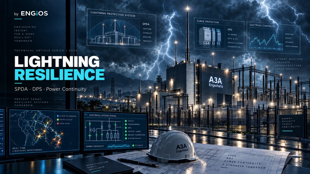
How severe storms and lightning affect continuity, and why LPS, SPDs, grounding and electrical protection must operate as an integrated system.
Check it out!
Severe storms can interrupt a critical facility through multiple paths at the same time: lightning, conducted surges, loss of external power, telecommunications failures, damage to sensitive electronics and unavailability of auxiliary systems. For this reason, electrical resilience does not depend on a single protection device. It results from coordination among the lightning protection system (LPS), surge protective devices (SPDs), grounding, equipotential bonding, electrical protection, power architecture, redundancy and operating procedures.
Engineering must begin with the failure mechanism. Lightning may strike the structure directly, occur nearby, induce overvoltages or produce effects conducted through power and telecommunications lines. The objective is to reduce the probability of damage, limit dangerous voltages, control current paths and preserve the critical services that depend on the electrical infrastructure.
A storm is an event; failure is a system problem
The same event can produce different consequences depending on the facility architecture. A building with an LPS may remain vulnerable if SPDs are absent or poorly coordinated, if equipotential bonding is inadequate, or if external interfaces are not included in the protection concept.
LPS, SPDs and grounding are complementary layers
The LPS addresses protection against the effects of lightning on the structure and its interfaces. SPDs limit transient overvoltages in circuits. Grounding and equipotential bonding help control potential differences and current paths. None of these layers should be analyzed in isolation.
The design must consider external interfaces
Electrical power feeds, metallic cables, telecommunications, antennas, external structures and security systems can carry disturbances into the facility. The analysis should map these interfaces and assess protection, routing, shielding, separation and equipotential bonding.
Redundancy does not solve shared overvoltage exposure
Two power sources, two switches or two devices may fail simultaneously if they share the same supply, the same potential reference or the same vulnerable route. Resilience requires true diversity and common-cause analysis.
How to procure the engineering scope
The scope should begin with risk analysis and the existing condition. Depending on maturity, it may include LPS design, SPD coordination, grounding, equipotential bonding, interface review, inspection, upgrades and commissioning.
In existing facilities, the first question is whether field conditions, interfaces and documentation still correspond to the originally designed system.
Assess the facility with Engineering Technical Due Diligence
A lightning discharge can enter through more than one path
Resilience analysis should not consider only a direct strike to the structure. Atmospheric events can produce effects through power lines, metallic telecommunications cables, external structures and potential differences among parts of the facility.
This explains why an apparently protected installation may continue to experience failures of controllers, power supplies, switches, cameras, automation equipment and communication interfaces during storms. The origin is not always the failed device itself, but the electrical path through which the disturbance entered.
The LPS protects the structure but does not replace internal protection
Air terminals, down conductors, grounding and equipotential bonding address fundamental aspects of a lightning event, but the continuity of electronic systems also depends on internal surge protection measures and coordination among interfaces.
In critical infrastructure, it is not enough to verify that an LPS exists. It is necessary to confirm whether the design represents the current building condition and whether expansions, antennas, photovoltaic panels, external equipment or new routes have changed the original scenario.
Coordination of internal protection
Surge protection needs to be analyzed throughout the electrical distribution system and at interfaces with sensitive equipment. The presence of devices at a single point does not demonstrate that the entire facility is protected.
The design should verify the relationship among the service entrance, intermediate panels, critical loads and signal circuits, documenting how the different protection layers work together.
Storms can interrupt power even without visible damage
A facility may go out of service because of protection trips, loss of external power, control failures or unavailability of auxiliary equipment without showing obvious structural damage. Post-event analysis therefore needs to consider protection records, alarms, power quality and the operating sequence.
When the cause is treated only as a “power outage,” the opportunity to identify the chain of failures that made the service vulnerable is lost.
Emergency power must be part of the same analysis
UPS systems and generator sets are continuity layers, but they depend on panels, automation, fuel, cooling and controls that may also be affected by the event. The resilience strategy must verify whether transfer and emergency operation remain available during adverse conditions.
Telecommunications and automation also carry risk
Communication routes, external links, controllers, sensors and supervisory systems may be affected during storms. A facility may retain power and still lose command, monitoring or communication capability.
The assessment should therefore map dependencies among electrical systems, telecommunications, automation, BMS, SCADA, video surveillance and access control. Shared interfaces must be recognized as possible common causes of unavailability.
Data Centers require coordination among multiple layers
In Data Centers and IT rooms, continuity simultaneously depends on power, cooling, networks and supervision. An electrical disturbance may trigger a chain that includes transfer to UPS, generator startup, a change in thermal operating conditions and loss of communication with field equipment.
The resilience design should assess the integrated behavior of the environment, not merely the individual presence of redundancies.
Photovoltaics and BESS expand the architecture and its interfaces
Photovoltaic generation and energy storage can increase autonomy and energy flexibility, but they also add equipment, circuits, external structures, supervision and new integration points. In a resilient facility, these interfaces must be included in protection and continuity analysis from the design stage.
The benefit of BESS or local generation depends on the ability to remain available when the external grid or other systems are degraded. Protection, control, auxiliary power and operating strategy therefore need to be consistent with the resilience objective.
Outdated documentation is a vulnerability
Expansions, renovations and replacements may alter the condition originally designed. Without drawings, technical descriptions, inspection records and identification of current interfaces, it becomes difficult to demonstrate that protection measures remain adequate.
For existing assets, as-built surveys and Due Diligence help reconcile documentation and field conditions before retrofit is defined.
Inspection must verify system condition and coherence
Effective inspections are not limited to observing isolated components. They need to verify whether the current configuration remains consistent with the design, whether connections and interfaces remain intact, whether later modifications were incorporated, and whether protection elements remain compatible with the systems they serve.
The history of events, failures and interventions is also evidence. Repeated damage to the same class of equipment may reveal an architectural vulnerability that does not appear in a visual inspection.
When the vulnerability lies in the protection architecture itself, the design must integrate risk analysis, LPS, grounding, equipotential bonding, surge protection and facility interfaces.
New design and retrofit require different strategies
In a new design, lightning and surge protection can be coordinated from the architecture stage, incorporating equipment location, routes, interfaces and continuity requirements. In brownfield environments, engineering must work with physical constraints, legacy systems and intervention windows.
The retrofit should prioritize the points with the greatest consequences and organize migration, upgrades and testing without compromising existing operations.
After upgrades, evidence must confirm that protection, emergency power, supervision and interfaces operate according to the defined requirements.
Commissioning closes the chain between design and continuity
A protection architecture needs to be verified after implementation. Commissioning organizes inspections, documentation, functional testing and evidence to demonstrate that installed systems correspond to the requirements defined in the design.
In critical facilities, verification should also consider the integrated response of emergency power, supervision and communications. The objective is to confirm that protection exists not only in drawings but is embedded in operations.
How to procure protection engineering and electrical resilience
The scope must match the asset’s maturity. A facility without reliable documentation may require survey and diagnosis before design. Another may require risk analysis, review of an existing design, LPS upgrades, internal protection, inspection or commissioning.
When the need is to develop or revise the protection system, the LPS Design should integrate risk, structure, interfaces, grounding, equipotential bonding and surge protection. The scope should define deliverables, professional responsibility, acceptance criteria and as-built documentation.
Compliance and resilience are not exactly the same question
Meeting standards requirements is indispensable, but a critical facility also needs to verify whether the architecture preserves its function when adverse conditions occur. Resilience analysis adds questions about operational consequence, redundancy, common causes, recovery time and dependencies among systems.
This prevents the conclusion that the mere presence of protection components demonstrates continuity. The objective is to verify whether the intended measures reduce the failure modes relevant to the service.
Common causes can eliminate entire redundancies
Two power feeds, two devices or two links may lose availability simultaneously when they share the same panel, route, environment, grounding system or external interface. Storms are particularly important in revealing these dependencies because a single disturbance can affect several elements in parallel.
The analysis should seek real diversity: different physical paths, independent sources when necessary, adequate route separation and the absence of single points whose failure neutralizes the entire redundancy.
External equipment and security systems also need to be included in the design
Cameras, access controllers, antennas, sensors, gates, barriers, field equipment and links can create interfaces between the external environment and internal networks. In critical facilities, these connections need to be recognized in the assessment of surges, grounding, power supply and continuity.
Losing video surveillance, access control or sensing during a storm can reduce operating capability precisely when environmental conditions are most severe. Protection of these systems should be consistent with their criticality and with the power and communications architecture.
Post-event analysis should produce engineering evidence
After a significant storm, protection records, alarms, equipment failures, utility events, maintenance interventions and operator reports help reconstruct the event sequence. This history can reveal failure paths that do not appear in a static inspection.
Recurrence analysis is especially useful. Repeated damage to power supplies, communication interfaces or equipment in the same area indicates that the issue may lie in the protection architecture rather than in the individual components being replaced.
Deliverables for an electrical resilience design need to be clear
The engagement should produce documentation usable during implementation and acceptance. Depending on scope, this may include risk analysis, surveys, drawings, technical descriptions, diagrams, specifications, protection criteria, interface records, a list of upgrades, a test plan and as-built documentation.
For existing assets, the diagnosis should identify condition, nonconformities, vulnerabilities and priorities. For new designs, it should state continuity requirements and criteria that allow the intended performance to be verified.
Acceptance criteria need to reflect the failure mode
Acceptance should not be limited to confirming that equipment was installed. Verification needs to demonstrate continuity of connections, consistency with the design, updated documentation and operation of associated systems.
When the intervention affects emergency power, automation or telecommunications, integrated tests are essential to show that the architecture responds as intended and that one protection measure has not introduced a new critical dependency.
Maintenance preserves protection throughout the life cycle
Physical changes, corrosion, third-party interventions, load expansion and equipment replacement can change system conditions. Inspections and documentation updates need to follow these changes.
Electrical resilience is a property of the system in operation. It degrades when the asset changes and engineering does not keep pace with the change.
An applied scenario shows the difference between component and system
Consider a facility with an LPS, an SPD at the service entrance, a UPS and a generator set. During a storm, the external grid experiences a disturbance; power transfers to the UPS, a transfer controller loses communication, and the generator does not assume the load within the expected time. At the same time, an external telecommunications interface fails.
In this scenario, no isolated component explains the unavailability. The analysis needs to reconstruct interfaces, auxiliary power, protection, communications, control logic and operating sequence. This system perspective is what distinguishes a resilience approach from a simple verification that equipment is present.
Field surveys should look for single points and shared paths
For existing assets, the survey needs to confirm power routes, panels, busbars, grounding connections, telecommunications entries, external equipment, redundancies and changes made since the original design. Updated diagrams help identify dependencies that are not visible in a point inspection.
The survey should also record where different systems share space, pathways or power. These overlaps can concentrate risk and guide the retrofit.
Maintenance and inspection plans need to track changes
An adequate architecture can lose performance when the facility is modified. New panels, photovoltaic expansion, equipment replacement, addition of antennas, route changes and civil renovations can create interfaces that did not exist in the original design.
Inspection and maintenance therefore need to be tied to change management. Relevant changes should trigger documentation review and, when necessary, a new risk assessment and review of protection criteria.
Indicators help identify loss of electrical resilience
Surge incidents, repeated power supply failures, protection trips, telecommunications unavailability, grounding anomalies, emergency interventions and discrepancies between field conditions and design are warning signs. Historical data makes it possible to identify trends before a higher-consequence failure occurs.
These indicators should feed asset management, maintenance and retrofit planning. Electrical protection stops being treated as a static installation and becomes a condition monitored over the life cycle.
Final considerations
The electrical risk of a storm must be analyzed by propagation path
A lightning discharge does not need to strike equipment directly to cause unavailability. Transient currents and overvoltages can reach a facility through the structure, electrical supply, metallic lines, telecommunications networks, external interfaces, automation systems, video surveillance, antennas, sensors and other conductors that cross boundaries between exposed areas and internal zones.
Engineering therefore needs to map entry and propagation paths. An analysis limited to air terminals and external down conductors may leave untreated precisely the interfaces that connect sensitive electronic equipment to the external environment. The objective of coordinated protection is to reduce the energy reaching each zone and keep voltages and currents within levels compatible with system withstand capability.
The Complete Guide to LPS + Lightning Protection Measures develops this system perspective in greater depth, while this article addresses the topic from the standpoint of operational continuity during severe storms.
External LPS and internal protection measures need to be designed as a set
The external LPS reduces risks associated with direct strikes to the structure, but systems continuity also depends on internal measures. Equipotential bonding, SPD coordination, adequate separation, routing, grounding, interface protection and the organization of lightning protection zones act on different mechanisms.
A facility may have compliant air terminals and down conductors and still suffer frequent outages of electronics, switches, controllers, video surveillance, access control or automation. This pattern normally indicates that the problem is not only lightning interception, but also how surges and potential differences enter and circulate through internal circuits.
The design needs to connect risk analysis, electrical architecture, surge protection, grounding and documentation. The LPS Design service should address these interfaces through engineering rather than merely position components.
SPD coordination is a system problem, not an isolated device choice
An SPD should not be specified solely by nominal discharge current or class. Coordination depends on its position in the system, required protection level, supply characteristics, equipment withstand capability, distance between stages, backup protection, grounding arrangement and actual current paths. An individual device may be correctly installed and still fail to protect the facility as expected if the rest of the architecture is inconsistent.
This point is especially important in facilities with distributed panels, power feeds to external equipment, telecommunications systems, Data Centers, industrial automation and buildings with multiple service entrances. Engineering must verify where transient energy is diverted, which potential differences may arise and whether there is coordination among service-entrance protection, intermediate panels and protection close to sensitive loads.
The technical comparison of NBR 5419 and the Electrical Studies Guide help deepen the standards and electrical coordination layer that supports this work.
Grounding and equipotential bonding reduce dangerous potential differences
Grounding should not be treated as a single resistance value obtained from an isolated measurement. For electrical resilience, the behavior of the overall system matters: interconnection of exposed conductive parts and other conductive elements, continuity of bonds, equipotential bonding, current paths and compatibility among the LPS, electrical installation, telecommunications and electronic systems.
During a lightning event, potential differences between subsystems can cause sparking, unwanted currents and damage even when each subsystem appears adequate on its own. Equipotential bonding reduces these differences and organizes the facility response as a coherent system.
For a deeper treatment, the Electrical Grounding eBook: Fundamentals, Design and Standards complements the topic with fundamentals, design and documentation.
Redundancy can fail simultaneously when the failure mode is common
Two redundant devices do not guarantee continuity if they share the same panel, route, grounding, external link, environment or surge path. Storms expose common-cause failures because one event can affect several layers at once: power, telecommunications, automation, cooling and external systems.
In a high-availability architecture, engineering needs to identify points where apparently independent redundancies converge. Two UPS systems may depend on the same incoming panel; two communications routes may share the same external enclosure; two chillers may depend on the same panel or BMS; two power sources may use the same protection or physical path.
This diagnosis connects lightning protection with Reliability and Availability Engineering: the objective is not merely to protect components but to prevent a single event from disabling functions that are intended to be independent.
Photovoltaics and BESS create new interfaces that need to be included in the study
Photovoltaic generation and storage can increase autonomy and energy flexibility, but they also add cables, converters, panels, communication links, metallic structures and DC/AC interfaces that need to be incorporated into the protection design. Expansion of an electrical system changes current paths and can make previous documentation insufficient.
In BESS, availability depends not only on electrical protection but also on PCS, BMS, EMS, cooling, communications and integration with the existing installation. In photovoltaics, external structures and long cable runs increase the importance of surge protection and equipotential bonding. The resilience benefit exists only when the new architecture is integrated, tested and documented.
The Complete BESS Engineering Guide complements this topic with sizing, safety, commissioning and operation.
Existing facilities need Due Diligence before any retrofit
In brownfield environments, the first step should not be choosing components. It is necessary to verify whether documentation represents the actual facility, identify expansions not incorporated into the original design, inspect conductor continuity, connections, equipotential bonding, SPD condition, external metallic interfaces and changes to roofs, façades, antennas, photovoltaic systems or telecommunications equipment.
Engineering Technical Due Diligence turns this survey into a traceable diagnosis: observed condition, nonconformities, vulnerabilities, evidence, criticality, recommendations and preliminary CAPEX. Without this step, there is a risk of designing on top of an incorrect as-built and preserving hidden failure paths.
When a facility has undergone successive expansions, the survey also needs to consider coordination among panels, selectivity, capacity, grounding and new cable routes. A storm may simply reveal a problem that was already latent in the architecture.
The design needs to deliver more than an air-terminal and down-conductor layout
A robust electrical protection and resilience scope should include applicable risk analysis, drawings, details, technical descriptions, SPD criteria, equipotential bonding, grounding interfaces, protection of incoming services, requirements for external equipment, coordination with electrical and telecommunications systems, and inspection and maintenance guidance.
In critical facilities, it is also advisable to record continuity assumptions: which loads cannot be interrupted, which electronic systems require additional protection, where redundancies exist and which points represent common-cause failure. This brings LPS design closer to critical-systems design.
The whitepaper on design and sizing of low-voltage electrical installations complements this perspective by structuring criteria, sizing and documentation for the associated electrical layer.
Commissioning should test the chain, not merely confirm visual installation
Visual inspection is necessary but insufficient to demonstrate readiness. Commissioning should verify continuity, connections, identification, protection coordination, device condition, consistency with design and documentation, and integration with systems that depend on the protected infrastructure.
In critical facilities, testing may include simulations of loss of external power, transfer to generators, alarm operation, UPS condition, BMS or SCADA communications, SPD monitoring and system behavior after power is restored. The objective is to verify that an electrical event no longer becomes a systemwide outage.
The Method for Commissioning, Verification and Acceptance of Electrical Installations provides a practical reference for planning evidence, tests and acceptance criteria.
Maintenance and inspection preserve effectiveness throughout the life cycle
Protection degrades when the installation changes and documentation does not keep pace. Roof renovations, installation of new equipment, photovoltaic expansion, panel replacement, changes in telecommunications routes, painting or corrosion of connections, grounding interventions and SPD replacement can modify expected performance.
Therefore, the maintenance plan needs to define periodic and extraordinary inspections after relevant events or configuration changes. Failure history should also feed back into engineering: recurring equipment damage, resets, loss of communications or frequent protection operation is evidence that the architecture deserves reassessment.
Calendar-based maintenance alone is not sufficient. Criticality, condition, exposure and event history need to influence the frequency and depth of verification.
Applied example: storm at a critical facility with a Data Center
Consider a site with a power service entrance, generator, UPS, redundant cooling, Data Center, video surveillance, access control and two telecommunications links. During a storm, the utility grid experiences a disturbance, a surge enters through an external service and an edge switch restarts. The generator starts correctly, but the loss of communications causes the BMS to lose supervision and part of the access system becomes unavailable.
The incident is not explained by a single component. The analysis needs to reconstruct the chain: surge origin, service-entrance protection, equipotential bonding, SPDs, switch power supply, grounding, data routes, link redundancy, BMS dependency and recovery sequence. The solution may involve protection design, route reconfiguration, redundant power, SPDs appropriate to specific interfaces, grounding review and integrated testing.
This example shows the value of systems engineering: the storm is the trigger; unavailability is the result of several dependencies. The design should address the mechanisms that turn the event into loss of service.
How to specify the procurement scope
A terms of reference or commercial scope should separate diagnosis, design, implementation and acceptance. For diagnosis, define document review, field survey, measurements, vulnerability matrix and technical report. For design, require analysis, technical descriptions, drawings, specifications, details and professional registration. For implementation, establish responsibilities for supply, execution, inspection and as-built updates. For acceptance, require a test plan, evidence, punch-list management and objective criteria.
This separation reduces ambiguity and allows contracting the stage compatible with asset maturity. In some cases, the client first needs Due Diligence; in others, sufficient diagnosis already exists to procure the LPS Design and associated electrical engineering directly.
Severe storms show why electrical protection must be treated as a system architecture. LPS, SPDs and grounding reduce different risks and need to operate in coordination with emergency power, telecommunications and electronic systems.
Technical references
[1] INSTITUTO NACIONAL DE PESQUISAS ESPACIAIS. Monitoring of the Territory: Lightning. São José dos Campos: INPE. Available at: https://www.gov.br/inpe/pt-br/acesso-a-informacao/perguntas-frequentes/principais-produtos-e-servicos-do-inpe/monitoramento-do-territorio-raios
[2] INTERNATIONAL ELECTROTECHNICAL COMMISSION. IEC 62305 Series — Protection against lightning. Geneva: IEC, 2026. Available at: https://webstore.iec.ch/en/publication/6797
Frequently asked questions
No. Equipment protection requires coordination with SPDs, grounding, equipotential bonding and treatment of power and telecommunications interfaces.
An LPS addresses lightning protection at the system and structure level; an SPD limits transient overvoltages in circuits. They are complementary layers.
Yes. Surges, protection trips, failures in panels, automation or telecommunications can interrupt internal systems even when the external grid remains available.
Complementary technical materials
Related services
- LPS Design
- Electrical Engineering Services
- Engineering Technical Due Diligence
- Retrofit and Upgrades
- Engineering Commissioning
Main content on this topic
Related technical content
- Complete Guide to Lightning Protection (LPS + Lightning Protection Measures)
- Guide to Electrical Studies in Power Systems
- Complete Guide to Low-Voltage Electrical Installations
- Complete Guide to Commissioning
- Electrical Grounding eBook
- Technical comparison ABNT NBR 5419:2015 vs. 2026
- Method for Commissioning, Verification and Acceptance of Electrical Installations
- Method for Design and Sizing of Electrical Installations
- Resilient Data Center: assessment, design, modernization and acceptance
- BESS: Complete Engineering Guide
