
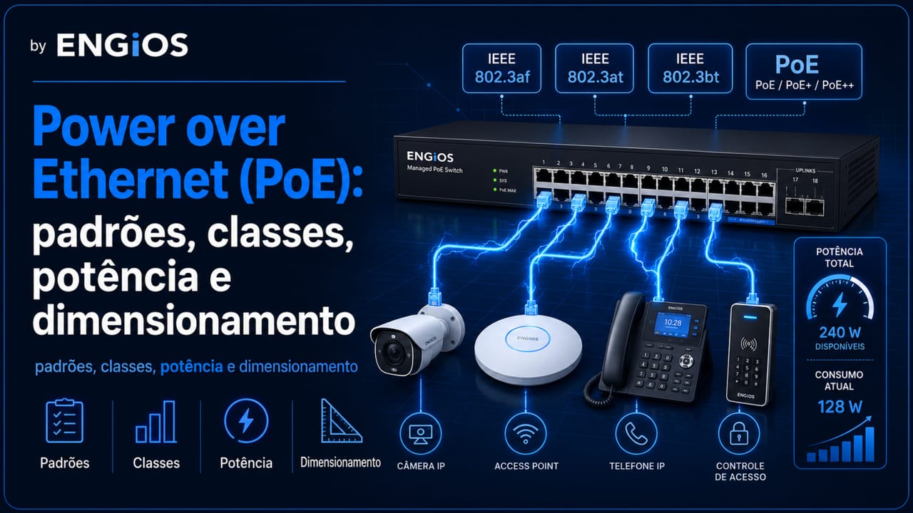
Understand Power over Ethernet: PoE, PoE+ and PoE++ standards, classes, PSE and PD, power budget, cabling, heating, UPS and testing.
Check it out!
Power over Ethernet, or PoE, is the technology that allows Ethernet data and direct-current power to be transmitted over the same twisted-pair cabling. It is used to power IP cameras, access points, phones, intercoms, access controllers, sensors, panels and other devices installed far from electrical outlets.
The convenience of using a single link does not eliminate the need for engineering design. Proper operation depends on compatibility between the power source and the device, the power actually available, channel losses, cable category and conductor gauge, temperature, cable bundling, electrical autonomy and testing criteria.
This article explains IEEE 802.3af, 802.3at and 802.3bt, the differences among PoE, PoE+ and PoE++, power classes, the roles of PSE and PD, and how to size an installation for enterprise networks, IP video surveillance, Wi-Fi and electronic security.
What is Power over Ethernet?
Power over Ethernet is a set of mechanisms that allows network equipment to supply electrical power to a remote device over the same copper channel used for communications. In standardized implementations, the power source identifies the presence of a compatible device before applying operating power.
PoE does not increase network speed. The data rate still depends on the Ethernet technology, equipment, cabling category and channel quality. PoE adds power delivery and the ability to manage that power centrally.
PSE: Power Sourcing Equipment
The PSE is the equipment that supplies power to the link. It is usually a PoE switch, but it can also be an injector or midspan installed between a non-PoE switch and the end device.
The PSE detects the device, identifies or negotiates the applicable power and monitors conditions such as overcurrent, disconnection and faults. The number of PoE ports alone does not indicate the total power the equipment can deliver.
PD: Powered Device
The PD is the device powered by PoE. Cameras, access points, IP phones, intercoms and biometric readers are common examples.
Declared consumption should be checked under different operating conditions. A PTZ camera may draw more power while moving, heating or activating illuminators. An access point may increase consumption when additional radios, USB ports or higher processing loads are active.
Endspan and midspan
In an endspan model, the switch itself acts as the PSE. In a midspan model, an injector adds power to the channel between the switch and the PD. Midspans can be useful in upgrades, but they add active components, connections, power feeds and points that must be documented and monitored.
How detection and power delivery work
In standardized PoE, the PSE should not apply operating power indiscriminately. It first performs PD detection. Then, depending on the type and supported features, power classification occurs and power delivery begins.
This process distinguishes IEEE PoE from passive solutions that keep voltage applied without the same negotiation. Passive PoE may use specific voltages and pinouts and should not be connected to equipment unless compatibility has been confirmed.
Classification and negotiation
Classification helps the PSE reserve an amount of power consistent with the PD requirement. The device can also provide additional information through mechanisms such as LLDP, depending on the implementation.
When negotiation does not occur as expected, the PD may operate with reduced features, reboot, fail to start or remain unavailable. The design should therefore verify the standard, class, PSE power and minimum power available at the PD.
Two energized pairs and four energized pairs
Early types use two pairs for power. Higher-power types defined in IEEE 802.3bt can use all four cable pairs. Four-pair power increases available power but also makes conductor resistance, current balance and bundle heating more important.
PoE standards: IEEE 802.3af, 802.3at and 802.3bt
The standards evolved to support devices with higher consumption. Commercial names such as PoE, PoE+ and PoE++ are useful, but the design should also record the IEEE type and required power.
| Type | Reference | Energized pairs | Maximum power at PSE | Approximate minimum power at PD |
| Type 1 | IEEE 802.3af | 2 | 15.4 W | 13 W |
| Type 2 | IEEE 802.3at | 2 | 30 W | 25.5 W |
| Type 3 | IEEE 802.3bt | 2 or 4, depending on class | 60 W | 51 W |
| Type 4 | IEEE 802.3bt | 4 | 90 W | 71.3 W |
The difference between PSE power and guaranteed PD power represents the losses allowed along the channel. The device’s nominal consumption should not be compared only with the maximum value advertised at the source.
Type 1: PoE
Type 1 supports lower-power devices such as phones, sensors, readers and some fixed cameras. Power available at the PD is lower than the 15.4 W supplied at the source.
Type 2: PoE+
Type 2 increases power for equipment such as cameras with additional features, access points and more demanding terminals. The term PoE+ is widely used to identify this generation.
Type 3 and Type 4: 4PPoE
IEEE 802.3bt introduced four-pair power and higher classes. This supports high-capacity access points, PTZ cameras, panels, collaboration devices, lighting and other higher-demand applications.
PoE classes and available power
Classes represent different power ranges. In newer types, classes extend from 1 to 8. For the design, the relevant value is not only the nominal port class but the power the PSE can sustain simultaneously across all planned ports.
| Class | Associated type | Maximum power at PSE | Approximate power available at PD |
| 1 | Type 1 | 4 W | 3.84 W |
| 2 | Type 1 | 7 W | 6.49 W |
| 3 | Type 1 | 15.4 W | 13 W |
| 4 | Type 2 | 30 W | 25.5 W |
| 5 | Type 3 | 45 W | 40 W |
| 6 | Type 3 | 60 W | 51 W |
| 7 | Type 4 | 75 W | 62 W |
| 8 | Type 4 | 90 W | 71.3 W |
Values should be confirmed in the PSE and PD documentation. Proprietary commercial names do not replace conformity and interoperability verification.
How to size the switch PoE budget
The PoE budget is the total power a switch can distribute among its ports. A 48-port unit may not be able to provide maximum power on every port simultaneously.
The calculation should start with the PD inventory and consider maximum consumption, quantity, simultaneity, growth, installed power supplies and redundancy mode.
Determine the maximum power of each device
For each PD, record:
- manufacturer and model;
- PoE standard and class;
- typical and maximum power;
- features that change consumption;
- reserve requirement;
- criticality and power priority.
Sizing from typical power can cause failures when the device reaches peak conditions.
Add the loads and apply margin
Consider an environment with 24 cameras at 12 W and six access points that can demand 25.5 W:
- cameras: 24 × 12 W = 288 W;
- access points: 6 × 25.5 W = 153 W;
- estimated load: 441 W.
With a 20% margin, the reference becomes approximately 529 W. The margin should be adjusted to risk, growth and device behavior; it should not be used to hide missing data.
Verify capacity with redundant power supplies
In modular switches or switches with redundant power supplies, available power can vary by operating mode. The design should confirm how much PoE remains available after loss of a power supply, module or external feed.
If the loss of one power supply forces the switch to shut down PoE ports, there should be a priority policy aligned with device criticality.
Distribute the load across switches and circuits
Concentrating all critical cameras, controllers or access points on one switch creates a failure domain. The design can distribute PDs across different switches, power supplies, UPS systems, circuits and technical rooms.
The PoE budget must be calculated together with the architecture, cabling and electrical continuity.
A3A sizes switches, power supplies, uplinks, power classes, UPS systems, racks and links within a documented and verifiable Telecommunications Design.
PoE switch, injector and PoE pass-through
The choice of power source depends on scale, management and architecture.
Managed PoE switch
This is usually the appropriate option for enterprise environments because it centralizes power and data, allows per-port consumption monitoring, device restart, alarms and policy enforcement.
The specification should consider total power, per-port power, supported types, power supplies, ventilation, temperature, uplinks, stacking, redundancy, SNMP, syslog and integration with the management platform.
PoE injectors
Injectors can serve an isolated point or upgrade an installation without immediately replacing the switch. In large quantities, however, they make power distribution more dispersed and complicate inventory, UPS coverage, supervision and maintenance.
PoE pass-through
Some devices receive PoE and provide part of that power to downstream equipment. Available power depends on what reaches the first device, its internal consumption and losses. The chain must be validated as a whole, not only through individual compatibility.
Cabling for Power over Ethernet
PoE uses balanced twisted-pair cabling, but current flow adds design criteria beyond data transmission.
Channel resistance and power drop
Conductor resistance causes dissipation and reduces the power available at the PD. Length, conductor gauge, temperature, connections and component quality affect the result.
Channels close to the distance limit, with thin patch cords or additional connections, deserve special attention. A 100 m limit does not mean every channel configuration will deliver the same power.
DC resistance unbalance
Current should divide properly among conductors. Excessive resistance differences within a pair or between pairs can reduce delivered power and affect transmission.
Inconsistent terminations, poorly seated conductors and unsuitable components can increase unbalance. For higher-power PoE applications, loop resistance and resistance-unbalance measurements should be included in the certification plan.
Category, conductor gauge and patch cords
Category indicates transmission performance, but physical construction also matters. Larger conductors have lower resistance. Patch cords with very small conductors increase losses and temperature.
Selection should consider category, AWG, temperature rating, shielding where applicable, length, number of connections and the manufacturer’s declaration for the intended PoE application.
Cable and connector heating
Current flow heats conductors. In bundles, heat generated by inner cables is harder to dissipate. Higher temperature increases attenuation and resistance, reducing electrical and transmission margins.
Number of cables per bundle
The design should assess the number of cables, current, energized pairs, conductor gauge, ambient temperature, pathway fill and ventilation. Large bundles with all four pairs energized require more rigorous analysis than small bundles with low loads.
Temperature and link length
Higher temperatures change cable performance and may require reducing maximum length according to standards, guides and manufacturer specifications. Spaces above ceilings, shafts, outdoor areas and unconditioned rooms should be considered.
Electrical arcing at connectors
Disconnecting a plug under load can create an arc at the contacts and degrade the connector. Components intended for PoE should support the expected cycles and currents. Maintenance procedures should avoid unnecessary disconnection under high load.
PoE applications
IP video surveillance
Fixed cameras may operate with Type 1 or Type 2, while PTZ models, illuminators, heaters and accessories may require higher classes. The design should analyze the highest-consumption condition, not only the typical value.
Centralizing power in switches and UPS systems helps maintain recording and monitoring during power failures. It also enables remote camera restart and per-port power monitoring.
Wi-Fi networks
Modern access points may use multiple radios, multigigabit ports, USB and advanced processing. Insufficient power can limit radios or features. The specification should relate data capacity, port speed and PoE class.
Telephony, intercom and access control
Phones, video intercoms, readers, controllers and biometric terminals can be network powered. The architecture should provide for call continuity, secure unlocking, emergency operation and behavior after communication loss.
Sensors, automation and smart buildings
PoE can power sensors, panels, lighting and automation devices. As more building functions depend on the switch, segmentation, redundancy, UPS, monitoring and change management become more important.
PoE integrates networking, video surveillance, Wi-Fi, intercom and access control — and must be treated as part of the complete system.
A3A develops integrated designs considering devices, power, autonomy, logical architecture, physical infrastructure and operating criteria.
PoE, UPS and operational continuity
Centralized power makes it possible to protect multiple PDs with a UPS installed in the technical room. However, runtime must consider switch consumption, PoE load, modules, uplinks, ventilation and system losses.
Runtime calculation
The load relevant to the UPS is not only the sum of the PDs. Measure or estimate:
- chassis and power-supply consumption;
- PoE power delivered;
- power-supply efficiency;
- other rack equipment;
- growth and failure conditions;
- required minimum runtime.
Independent feeds and pathways
Two redundant switches connected to the same UPS, circuit or panel still share a failure point. Critical systems may require independent power supplies, UPS systems, circuits and physical routes.
Port priority
Some switches allow ports to be prioritized when available power decreases. Critical cameras, controllers, access points in essential areas and emergency telephony should be classified according to the operating plan.
PoE management and monitoring
Monitoring should make it possible to identify consumption, allocated power, class, port state, negotiation failures and overload events.
SNMP, syslog and telemetry
Management platforms can collect power per port and per switch, budget availability, alarms and changes. Syslog records connection, power-denial and restart events.
Consumption trends help identify growth, defective equipment, profile changes and shrinking margin.
LLDP and PD information
LLDP can enable exchange of additional information about identity and power. The protocol does not eliminate the need for an inventory, but it improves visibility and negotiation when PSE and PD are compatible.
Remote restart
Turning a port’s power off and back on can recover a stalled PD. This feature should be controlled, logged and used after analysis, because frequent power cycles can hide cabling, firmware, temperature or capacity problems.
Common failures in PoE installations
- considering only the number of ports and ignoring the total power budget;
- using typical instead of maximum consumption;
- mixing standardized and passive PoE without documentation;
- sizing the switch without considering power-supply failure;
- installing cables and patch cords with high resistance;
- ignoring bundle heating;
- not measuring resistance unbalance;
- concentrating all critical devices on one PSE;
- undersizing UPS systems and circuits;
- not monitoring consumption and alarms;
- accepting the installation simply because the PD powered on;
- not recording class, port, cable and device in the as-built documentation.
End-to-end PoE sizing: from the PSE to the device
Correct sizing does not end with the switch PoE budget. Engineering must verify the complete chain between the rack AC supply and the power actually usable by the PD. This includes the switch power supply, reserve for the equipment itself, power-allocation policy, channel current, conductor resistance, connections, temperature and device operating condition.
Advertised power, allocated power and consumed power
Three values should not be confused. Maximum port power is the limit the PSE can provide for a given class. Allocated power is the value the switch reserves for the PD according to classification or negotiation. Consumed power is what the device actually uses at a given moment.
Under normal operation, measured consumption can be much lower than the maximum. This does not mean the design should be based only on the average: during startup, motor operation, heaters, illuminators, USB ports, additional radios or intensive processing, some devices increase demand. The design value must reflect the real operating envelope.
Channel losses are part of the equation
Some of the power delivered by the PSE is dissipated in the cabling. Physically, voltage drop increases with current and path resistance, while resistive dissipation increases approximately with the square of current. Higher-power applications therefore make conductor gauge, length, temperature and termination quality even more important.
Two links in the same category can have different thermal behavior if they use different conductor gauges, thin patch cords, more connections or are installed in hot environments. Transmission category does not replace analysis of the channel’s physical construction.
Example budget with growth and contingency
Consider a rack with 32 cameras with a maximum consumption of 14 W, eight access points that can reach 28 W and four controllers at 10 W. Maximum PD demand is 712 W. If the design allows for growth of six cameras and two access points, the expansion adds 140 W, bringing the reference to 852 W.
This value is still not the final switch specification. It is necessary to verify how much the PSE must supply to guarantee the required PD power, the power available with all installed power supplies, how much remains after a planned failure and how ports will be prioritized in a degraded condition. If the equipment operates with N+1 power-supply redundancy, the failure condition must be tested with the planned load rather than inferred only from the power-supply nameplate rating.
| Check | Design question | Evidence |
|---|---|---|
| PD | What is the maximum power with all features active? | Datasheet and functional test |
| PSE | What total power remains available in the actual power-supply configuration? | Specification and equipment reading |
| Channel | Does the cabling deliver power with acceptable resistance and temperature? | Certification and load test |
| UPS | Does runtime account for the switch, PoE load and losses? | Calculation report and test |
| Failure | Which ports remain powered after loss of a power supply or circuit? | Contingency test |
PoE in existing networks: retrofit, brownfield and hidden limitations
Upgrading a network to power new PoE devices requires more than replacing the switch. In older installations, cabling may have been designed for data transmission with much lower or no current, and previously irrelevant problems may appear as power increases.
Baseline of existing cabling
Before migration, record the category, manufacturer when identifiable, conductor gauge, length, number of connections, patch cords, termination condition, existing certifications and pathway temperature. Missing documentation should be treated as a design uncertainty, not as evidence of compliance.
Links with oxidized connectors, poor terminations, partially damaged pairs or high resistance may still carry data but show power drop, heating or instability when subjected to higher PoE classes.
CCA and components without traceability
CCA cables, made with copper-clad aluminum conductors, have higher resistance than equivalent solid-copper conductors and should not be accepted as generic substitutes in a system requiring standardized performance and power delivery. In a retrofit, discovering materials without traceability may justify selective replacement before PoE expansion.
Bundles, pathways and temperature
An expansion can increase not only the number of devices but also the number of cables energized simultaneously in the same bundle. Saturated cable trays, hot ceiling spaces and poorly ventilated shafts increase overall temperature. The analysis should consider the future condition, including after reserve capacity is occupied.
The article on Network Infrastructure Upgrade presents the brownfield diagnosis, baseline, retrofit design and phased migration methodology.
How to troubleshoot PoE faults without swapping equipment by trial and error
PoE faults can be mistaken for network, firmware or application problems. Troubleshooting should separate power delivery, the data link and PD behavior, collecting evidence before restarting or replacing components.
| Symptom | Priority hypotheses | Check |
|---|---|---|
| PD does not power on | detection, incompatible class, port without PoE, cable fault | port state, LLDP, PoE tester, continuity |
| PD powers on with reduced features | insufficient negotiated power | class, allocated power, logs and datasheet |
| Reboots under peak load | budget, voltage drop, power supply or UPS | per-port consumption, load test, PSE events |
| Failure after heating | resistance, bundle, environment, connector | temperature, loop resistance and inspection |
| Intermittent fault on one link | termination, patch cord, DC resistance unbalance | certification and controlled component substitution |
| Multiple ports drop together | power supply, total budget, circuit or UPS | alarms, available power and failure domain |
Network Troubleshooting should be applied together with PoE troubleshooting when the symptom also involves packet loss, interface errors, Ethernet negotiation, VLANs or applications. PoE and data share the same physical channel but require different metrics.
How to specify PoE in design and procurement
A specification that requires only a “48-port PoE+ switch” leaves critical variables open. Two devices with the same number of ports can differ significantly in total budget, per-port power, power supplies, capacity under redundant conditions, telemetry and prioritization policies.
The design specification should define, as applicable:
- required IEEE types and classes per port;
- minimum PoE budget with the supplied power-supply configuration;
- minimum remaining capacity under the specified failure condition;
- number of ports that must simultaneously deliver each class;
- negotiation and interoperability mechanisms;
- per-port power monitoring and alarms;
- priority policy under low-power conditions;
- UPS and runtime requirements;
- minimum cabling and patch-cord characteristics;
- resistance and unbalance tests where applicable;
- load test and acceptance criteria;
- as-built documentation linking PSE, port, link and PD.
In public tenders or private competitive procurements, these requirements allow alternatives to be compared by performance and reduce dependence on commercial names such as “PoE++”, “UPOE” or other proprietary terms. Interoperability should be demonstrated by required compliance and effective PSE-to-PD compatibility.
PoE must become a measurable design requirement, not just an acronym in a datasheet.
Specification, power budget, cabling, UPS, equivalence criteria and the test plan should be defined before switches and devices are purchased.
PoE testing and commissioning
Acceptance should demonstrate that the source, channel and device operate under the intended conditions.
PSE and PD verification
Confirm standard, type, class, available power and required power. Record negotiation status and observed consumption under normal and peak conditions.
Cabling certification
In addition to transmission parameters, the test plan may include loop resistance, within-pair unbalance and pair-to-pair unbalance. Results should be associated with the link identifier.
Load testing
A tester capable of applying a load helps verify whether the PSE and channel deliver the advertised power. Merely detecting voltage or class does not demonstrate behavior under demand.
Failure and runtime testing
In a controlled manner, simulate loss of a power-supply member, loss of input power, switch restart and UPS operation. Verify which ports remain powered, how long transitions take and whether systems recover automatically.
As-built documentation
The as-built documentation should record switch, slot, port, standard, class, power, PD, cable identification, rack, UPS, priority and test results. This documentation reduces troubleshooting time and supports future expansion assessments.
An energized port does not prove the PoE system complies with the design.
Acceptance should validate power under load, negotiation, cabling, alarms, redundancy, runtime and device recovery.
Conclusion
Power over Ethernet simplifies deployment and centralizes power, but it must be treated as part of the network architecture and electrical infrastructure. Compatible standards, PD power, total budget, cabling, temperature, UPS, monitoring and testing determine whether the system will operate reliably.
Correct specification prevents devices from operating with reduced features, reboots, intermittent faults, overheating and loss of runtime. In enterprise networks and critical systems, PoE should be sized, documented and commissioned like any other engineering subsystem.
Technical references
[1] IEEE. IEEE Std 802.3bt-2018 — Physical Layer and Management Parameters for Power over Ethernet over 4 pairs. New York: IEEE, 2018. Available at: https://standards.ieee.org/ieee/802.3/5084/.
[2] ETHERNET ALLIANCE. PoE Certification Program. Beaverton: Ethernet Alliance. Available at: https://ethernetalliance.org/poecert/.
[3] CISCO. What Is Power over Ethernet (PoE)? San Jose: Cisco Systems. Available at: https://www.cisco.com/site/us/en/learn/topics/networking/what-is-power-over-ethernet.html.
[4] TELECOMMUNICATIONS INDUSTRY ASSOCIATION. ANSI/TIA-568.2-E and ANSI/TIA-568.5-1. Arlington: TIA, 2024. Available at: https://tiaonline.org/standardannouncement/tia-publishes-new-standards-ansi-tia-568-2-e-and-ansi-tia-568-5-1/.
[5] INTERNATIONAL ORGANIZATION FOR STANDARDIZATION; INTERNATIONAL ELECTROTECHNICAL COMMISSION. ISO/IEC 11801-1:2017 — Information technology — Generic cabling for customer premises — Part 1: General requirements. Geneva: ISO/IEC. Available at: https://www.iso.org/standard/66182.html.
[6] BRAZILIAN ASSOCIATION OF TECHNICAL STANDARDS. ABNT NBR 14565: structured cabling for commercial buildings. Rio de Janeiro: ABNT.
[7] BRAZILIAN ASSOCIATION OF TECHNICAL STANDARDS. ABNT NBR 16869: structured cabling. Rio de Janeiro: ABNT.
[8] BRAZILIAN ASSOCIATION OF TECHNICAL STANDARDS. ABNT NBR 17040: equipotential bonding of telecommunications cabling infrastructure. Rio de Janeiro: ABNT.
Frequently asked questions
Power over Ethernet is the technology that transmits data and direct-current power over the same Ethernet cable to power devices such as cameras, access points, phones and controllers.
PoE generally refers to IEEE 802.3af, PoE+ to 802.3at and PoE++ to the higher-power types of IEEE 802.3bt. The design should confirm the type, class and power available at the PD.
Not necessarily. A switch has a total power budget that may be lower than the sum of the maximum power of all ports. Simultaneous load must be calculated and installed power supplies verified.
Compatibility depends on category, construction, resistance, conductor gauge, length, connections, temperature and channel condition. Higher-power applications require attention to heating and resistance unbalance.
IEEE 802.3bt Type 4 allows up to 90 W at the PSE output and approximately 71.3 W minimum at the PD, accounting for allowed channel losses.
No. Passive solutions may keep voltage applied without the standardized detection and negotiation process. They should only be used when source, voltage, pinout and device are proven compatible.
Add the maximum power of devices that will operate simultaneously, apply an appropriate margin, and confirm that the switch maintains that capacity with the actual power-supply and redundancy configuration.
A UPS is recommended when cameras, telephony, Wi-Fi, access control or other devices must continue operating during power failures. Runtime should account for the switch, PoE load and other rack equipment.
Acceptance should verify the standard, class, power, negotiation, consumption, cabling, resistance, unbalance, delivery under load, alarms, runtime and behavior during failures.
Complementary technical materials
Continue the learning path according to the project stage: architecture and sizing, infrastructure and certification, applications, or methodological depth.
Architecture, design and sizing
- Enterprise Network Architecture — layers, redundancy, capacity, security and operation.
- Network Design — survey, requirements, documentation, deployment and acceptance.
- Network Infrastructure — racks, cabling, power, active equipment and system interfaces.
Cabling, installation and certification
- Network Cable Certification Parameters — performance, resistance and channel test criteria.
- MPTL in Structured Cabling — direct device connection and design considerations.
- Complete Guide to Structured Cabling — standards, components, design and certification.
PoE applied to video surveillance and electronic security
- IP Video Surveillance — architecture, cameras, network, recording and power.
- Infrastructure for IP Video Surveillance Systems — switches, links, racks, UPS and availability.
- Complete Guide to Video Surveillance Systems — integrated view of design, deployment and operation.
Guides and decision-support materials
- Complete Guide to Network Architecture — broad view of topologies, layers and infrastructure.
- Whitepaper: design, technical standardization and cost reduction — how engineering reduces improvisation and rework.
- eBook: why commission a Structured Cabling Design — criteria for procuring, deploying and validating the infrastructure.
