
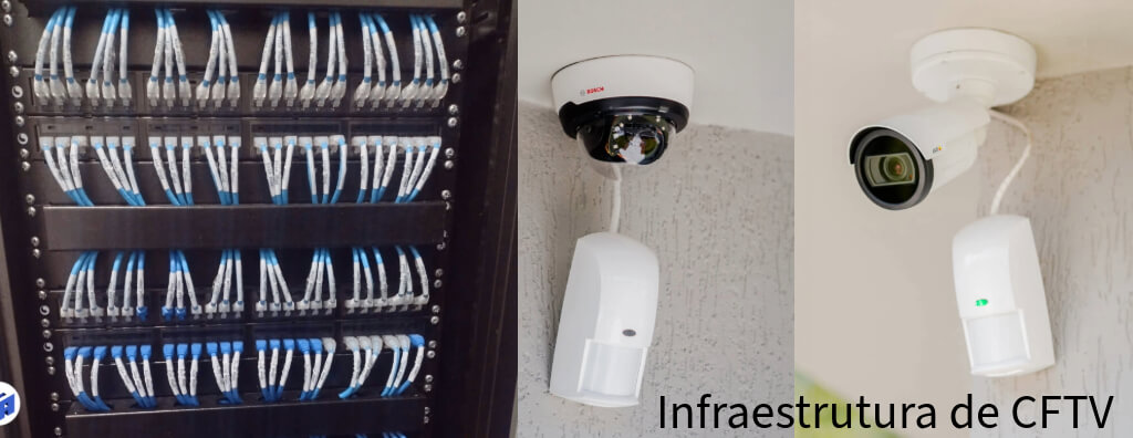
IP video surveillance infrastructure: how to size cameras, PoE, switches, cabling, MPTL, uplinks, fiber, VMS, servers, storage, cybersecurity, certification and As-Built documentation.
Check it out!
IP video surveillance infrastructure is the set of physical and logical systems that enables camera video streams to be transported, powered, processed, recorded, stored and made available. It includes structured cabling, PoE, access switches, uplinks, backbone, fiber optics, racks, VMS servers, storage, time synchronization, network segmentation, electrical protection and documentation.
In small systems, this architecture may appear simple. In corporate, industrial, institutional or mission-critical installations, however, video surveillance is no longer just a collection of cameras and becomes a distributed platform. Performance depends on the integration of network, power, processing and storage. A high-quality camera connected to poorly sized infrastructure still produces a fragile system.
Basic architecture of an IP video surveillance system
The most common physical flow starts at the camera, crosses the access link to a PoE switch, continues through uplinks and backbone to the distribution/core layer, and reaches management, recording and storage servers.
Each segment has its own requirements. The camera link must meet cabling and PoE requirements; the switch must support power and traffic; the uplink must absorb the sum of the streams; the server must process recordings; storage must sustain continuous writes and retention; and the operator workstation must receive the required streams without overloading the system.
IP cameras: the source of the data
An IP camera captures, encodes and transmits video over the network. Depending on the model, it may also generate audio, events, metadata, analytics and multiple streams with different resolutions and rates.
The generated traffic is not defined by resolution alone. Bitrate depends on:
- codec, such as H.264 or H.265;
- frame rate;
- compression quality and profile;
- CBR, VBR or maximum bitrate limits;
- scene complexity;
- motion;
- image noise and lighting;
- number of simultaneous streams;
- analytics and metadata.
For this reason, it is not technically appropriate to size the network using only “how many megapixels the camera has.” The design should use manufacturer data, the operating scenario and engineering margins.
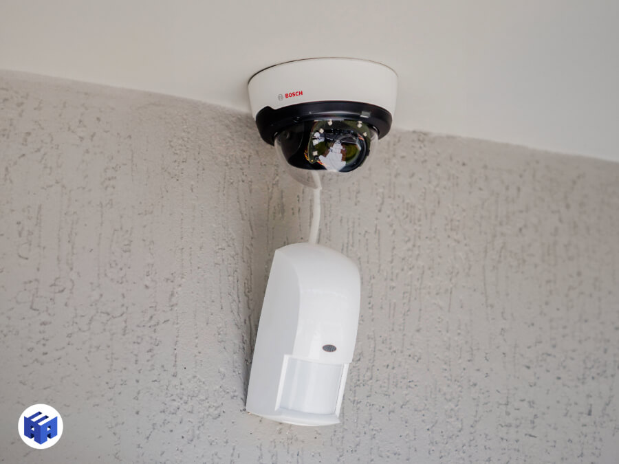
A3A Engenharia collection — IP camera integrated into the security infrastructure.
Camera bitrate vs. link capacity
A camera bitrate generally uses only a fraction of the capacity of a Fast Ethernet or Gigabit Ethernet link. Bottlenecks arise more often when multiple streams are aggregated at a switch or uplink.
If twenty cameras generate 8 Mb/s each, the nominal sum is 160 Mb/s before accounting for overhead, additional streams, viewing, failover and growth. In a system with hundreds of cameras, uplinks and servers become critical points.
The design should work with average and maximum bitrate because high-motion scenes can temporarily increase traffic in VBR systems. Sizing only by the average can cause congestion during events precisely when video is most important.
PoE switches: network and power in the same device
A PoE switch for video surveillance is not selected only by port count. PoE budget, uplinks, switching capacity, redundancy and environment determine how many cameras the device can actually sustain.
The PoE switch should not be selected only by the number of ports. It must simultaneously meet:
- switching capacity;
- uplink speed and quantity;
- PoE standard and power per port;
- total PoE budget;
- power-supply redundancy when required;
- VLANs and management features;
- monitoring and logs;
- installation temperature and environment;
- optical uplinks compatible with the backbone.
A PTZ camera, IR illuminator or device with a heater may require significantly more power than a simple fixed camera. The design should use the expected maximum consumption and verify the degraded operating condition of the switch when redundant power supplies are used.
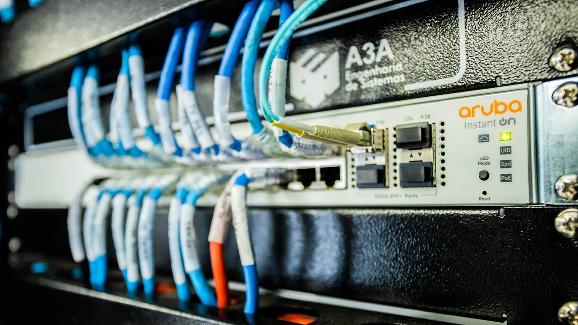
A3A Engenharia collection — PoE switch and cabling in a telecommunications rack.
Power over Ethernet and cabling sizing
PoE carries power over the same pairs used for data. This adds resistive losses and heating to the link. In bundles with many energized cables, temperature, conductor gauge, resistance and grouping must be considered.
Cable category does not replace this analysis. A poorly specified Cat6 cable may have less favorable thermal behavior than another product in the same category. The design must consider construction, conductor material, rated temperature and manufacturer recommendations.
CCA products — copper-clad aluminum — should not be treated as equivalent to copper cables specified for structured cabling. In addition to compliance concerns, their higher electrical resistance is undesirable for PoE.
Horizontal cabling for cameras
The access link may use Cat5e, Cat6, Cat6A or another solution according to requirements. For new projects, Cat6 is often adopted because it provides a good performance margin and life cycle. Cat6A may be used when the project strategy requires greater capacity, 10GBASE-T over 100 m, or converged standardization.
Camera resolution does not define the category. A 4K camera can operate over a compliant Cat5e link; the design should consider the Ethernet application, PoE, environment, certification and future expansion.
MPTL in IP video surveillance
Cameras are fixed devices and are often installed in boxes or locations with limited space. MPTL — Modular Plug Terminated Link can eliminate the telecommunications outlet and patch cord at the camera end.
The solution must use a field-terminable plug compatible with the horizontal cable, category, construction and any shielding. MPTL is not simply crimping an ordinary plug onto solid cable. The link must be certified using the appropriate test configuration.
Racks and telecommunications cabinets
The rack organizes patch panels, switches, fiber distribution panels, power supplies, UPS systems, cable managers and other elements. In distributed video surveillance, intermediate racks reduce horizontal cable lengths and allow PoE to be brought closer to the cameras.
The design should verify:
- rack-unit space;
- ventilation and heat dissipation;
- electrical power;
- UPS and autonomy;
- grounding and equipotential bonding;
- cable entry and exit;
- horizontal and vertical cable management;
- capacity reserved for expansion;
- access control to the technical room.
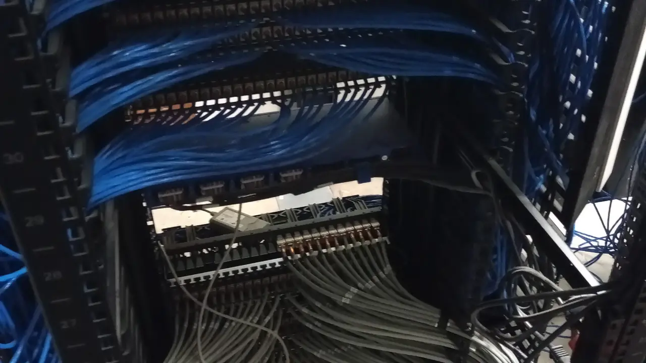
A3A Engenharia collection — rack and cabling in mission-critical infrastructure.
Uplinks and backbone: where traffic is aggregated
The switch uplink concentrates traffic from multiple cameras. Therefore, it must be sized by the sum of the streams, not by the speed of an individual port.
A topology with multiple access switches connected to a core may require 1, 10 or more Gb/s uplinks, depending on the number of cameras, bitrate, streams and redundancy. In large installations, fiber optics is normally preferred for the backbone because of capacity, distance and electromagnetic immunity.
Redundancy should be designed according to criticality. Having two links does not automatically mean high availability; topology, protocol, physical paths, switches, power supplies and shared dependencies must be verified.
Fiber optics in video surveillance
Fiber optics is especially relevant for:
- interbuilding links;
- campuses and large areas;
- industrial yards;
- environments with strong EMI;
- runs beyond practical copper limits;
- high-capacity backbones;
- architectures that need to break galvanic connections.
Fiber does not provide PoE to the camera. Therefore, the architecture may use an optical backbone to a local cabinet and copper/PoE for final access. This combination often balances reach, immunity and operational simplicity.
Logical network: VLANs and segmentation
Although cabling is physical, IP video surveillance requires logical planning. VLANs help separate domains, control access and organize operations. The design should consider communication among cameras, VMS, servers, clients, integrated systems and infrastructure services.
Segmentation should not be confused with complete security. Firewalls, ACLs, authentication, credential management, firmware updates and access policies remain necessary.
QoS: when it makes sense
QoS can prioritize certain traffic types on shared networks, but it does not replace capacity. If a link is permanently saturated, prioritization merely determines which flow suffers more.
On a dedicated video surveillance network with adequate headroom, QoS may play a secondary role. On converged networks carrying voice, data, video and critical systems, prioritization policies may be relevant. The design should start from the actual traffic model.
Multicast and video distribution
In certain architectures, multicast reduces stream duplication when multiple workstations need to view the same camera. However, it requires correct switch, IGMP and distribution-domain configuration.
Poorly configured multicast can flood ports and create unnecessary traffic. Therefore, its adoption should be aligned with the VMS and camera manufacturer rather than applied as a generic rule.
VMS: the management layer
The Video Management System (VMS) manages cameras, users, events, recording, playback, maps and integrations. In enterprise architectures, functions may be distributed among different servers: management, recording, event, mobile, analytics and database.
Sizing should consider the number of cameras, bitrate, recording, simultaneous clients, failover, analytics and integrations. A generic requirement for a “video surveillance server” is not sufficient for procurement.
Recording servers
The recording server receives streams, writes them to storage and serves playback requests. Bottlenecks may be in the network, CPU, memory, storage controllers or disk I/O.
The specification should verify:
- number of cameras per server;
- total incoming bitrate;
- outgoing bitrate for playback/export;
- codec and processing;
- network interfaces;
- storage architecture;
- failover;
- VMS manufacturer requirements.
A platform with a powerful processor can fail if the storage subsystem cannot sustain continuous writes.
Storage: retention, throughput and resilience
Storage is sized by the amount of data recorded over the retention period. The calculation should consider bitrate, recording hours, recording policy, overhead, reserve capacity and availability.
Capacity in terabytes is only one part of the problem. The system must also sustain write and read throughput, RAID rebuilds, exports and disk failures.
RAID improves disk-failure tolerance according to the selected architecture, but it is not backup. The strategy should consider criticality, retention, evidentiary requirements and preservation policies.
Edge storage and distributed recording
Some cameras support local storage on a card or internal memory. This feature can serve as a buffer or recovery mechanism during temporary network interruptions, depending on the solution and VMS.
The architecture should define how synchronization occurs after communication is restored and which events are preserved. It should not be assumed that every edge-storage implementation provides equivalent automatic failover.
Time synchronization
An incorrect timestamp compromises investigations, correlation among cameras and integration with access control or alarm systems. The infrastructure should provide synchronization via NTP or a compatible mechanism, with reliable sources and consistent policies.
In critical environments, availability of the time service must also be considered. Isolated cameras with divergent clocks reduce evidentiary value and make event analysis more difficult.
Outdoor cameras: protection beyond the network
Cameras on façades, roofs, poles and yards are exposed to conditions different from indoor environments. In addition to the enclosure protection rating, the design should evaluate:
- temperature and solar radiation;
- humidity and condensation;
- surges and lightning;
- interface with the lightning protection system;
- potential differences;
- protection of power and signal lines;
- outdoor-rated cables;
- transition to fiber where appropriate.
Cable shielding is only one possible measure. In some cases, fiber is technically superior because it eliminates the metallic path.
EMC and shielded cabling in video surveillance
Industrial environments or routes near power systems may justify F/UTP, U/FTP or S/FTP. However, a shielded system requires continuity across cable, connectors, panels and patch cords, as well as correct integration with equipotential bonding.
Generic rules such as “ground at one end” should not replace engineering design. ABNT NBR 17040 should be considered for equipotential bonding of telecommunications infrastructure.
Availability: identifying failure domains
High availability requires mapping what happens when each component fails. A single switch can take dozens of cameras offline; a single uplink can isolate a building; a single power supply can remove PoE from an entire area; a single storage system can compromise recording for hundreds of channels.
The design should analyze failure domains and criticality. Depending on requirements, it may provide:
- redundant switches;
- redundant uplinks;
- redundant power supplies;
- diverse physical paths;
- recording servers in failover;
- resilient storage;
- UPS and generator;
- physical distribution of cameras across devices.
Cybersecurity in IP video surveillance
Cameras are network devices and must be treated as IT/OT assets. Relevant measures include:
- individual credentials and password policies;
- disabling default accounts;
- firmware updates;
- segmentation;
- control of ports and services;
- certificates where supported;
- restricted administrative access;
- logs and monitoring;
- secure remote access.
Security should not depend on a “closed network.” Integrations, maintenance laptops, remote access and shared services create paths that must be governed.
Physical design and pathways
Cable trays, conduits, shafts, boxes and supports affect video-surveillance reliability. Undersized pathways make cable installation difficult, increase compression and prevent expansion.
The design should coordinate video surveillance with electrical systems, lightning protection, HVAC, architecture and other systems. Routes that appear available on drawings may conflict with ducts, trays or structural elements during construction.
Cabling certification
An available camera image does not prove link compliance. Certification provides objective evidence about the physical layer and should be tied to each point’s identification.
Each permanent link should be tested according to the specified standard and category. Certification evaluates electrical parameters that cannot be inferred merely from the existence of an Ethernet link.
Results should be linked to the physical identification of the point. The certifier’s native file, together with reports and calibration records, strengthens acceptance traceability.
Cabling testing is not system testing
Certification confirms the physical medium. Video-surveillance commissioning must validate the operational function. Tests include:
- connectivity and PoE;
- image and focus;
- field of view;
- frame rate and compression;
- recording;
- retrieval and playback;
- alarms and events;
- analytics;
- failover;
- time synchronization;
- integration with other systems.
A cable can pass certification while the camera fails because of configuration; a camera may temporarily work over a link that is out of specification. The two layers must be accepted separately.
As-Built documentation and identification
Each camera must have an unambiguous relationship with the network point, switch, port, rack, circuit and physical position. The As-Built must record the condition actually installed rather than reproducing the original design without validation.
Minimum documentation may include:
- camera location plan;
- point and cable identification;
- racks and patch panels;
- switches and ports;
- backbone topology;
- addressing and VLANs according to the documentation policy;
- VMS and storage diagrams;
- certification reports;
- relevant configuration parameters;
- asset inventory.
Procurement: how to specify infrastructure without locking in a brand
A robust technical package defines performance and interfaces. For switches, for example, port count, PoE capacity, uplinks, management features and environment should be specified instead of copying a manufacturer’s datasheet without justification.
For servers and storage, requirements should derive from the VMS workload. For cabling, category, construction, conductor, fire reaction, environment and certification must be clear.
Equivalence analysis should compare what was required with what the supplier actually offered, recording deviations before procurement and installation.
Future expansion
Video-surveillance systems tend to grow. Infrastructure should provide coherent reserves in:
- switch ports;
- PoE budget;
- uplinks;
- fiber strands;
- rack space;
- storage capacity;
- VMS licenses;
- pathways and physical infrastructure;
- addressing and segmentation.
Excessive reserve also has a cost. Engineering should define the growth horizon and scenarios, avoiding both early saturation and purposeless oversizing.
IP video surveillance infrastructure design checklist
Before finalizing the design, confirm:
- all cameras have defined bitrate and PoE requirements;
- switches have sufficient ports, power and uplinks;
- uplinks support aggregated traffic with margin;
- the backbone has been sized and uses an appropriate physical medium;
- racks, power and cooling have been verified;
- VMS and servers meet the expected workload;
- storage meets capacity and throughput requirements;
- VLANs, access and cybersecurity have been defined;
- outdoor cameras have a protection strategy;
- cabling has specified category, environmental suitability and certification;
- the test plan separates certification from commissioning;
- As-Built documentation and identification are part of acceptance.
Final considerations
A high-performance IP video surveillance infrastructure starts with coordination among the physical network, logical network, PoE, backbone, servers, VMS, storage, power, protection and documentation. No isolated component guarantees the result.
Designing only the number of cameras and buying switches “with enough ports” is insufficient. The system must be modeled by traffic flows, power, aggregation, availability, retention and operational criticality.
When infrastructure is planned as systems engineering, video surveillance becomes scalable, auditable and easier to maintain. When it is treated only as camera installation, bottlenecks appear in the uplink, PoE, storage or documentation — usually after construction is already complete.
Acceptance of an IP video surveillance system should integrate network, recording, storage, events and documentation. Commissioning only the camera leaves the solution’s main failure domains unvalidated.
Technical references
[1] INTERNATIONAL ELECTROTECHNICAL COMMISSION. IEC 62676 — Video surveillance systems for use in security applications. Available at: https://www.iec.ch/
[2] IEEE. IEEE 802.3 Ethernet Working Group — Ethernet and Power over Ethernet. Available at: https://www.ieee802.org/3/
[3] ASSOCIAÇÃO BRASILEIRA DE NORMAS TÉCNICAS. ABNT NBR 14565 — Structured cabling for commercial buildings. Available at: https://www.abntcatalogo.com.br/
[4] ASSOCIAÇÃO BRASILEIRA DE NORMAS TÉCNICAS. ABNT NBR 16869 — Structured cabling. Available at: https://www.abntcatalogo.com.br/
[5] ASSOCIAÇÃO BRASILEIRA DE NORMAS TÉCNICAS. ABNT NBR 17040 — Equipotential bonding of telecommunications infrastructure. Available at: https://www.abntcatalogo.com.br/
[6] INTERNATIONAL ORGANIZATION FOR STANDARDIZATION; INTERNATIONAL ELECTROTECHNICAL COMMISSION. ISO/IEC 11801 — Generic cabling. Available at: https://www.iso.org/
Frequently asked questions
Cameras, cabling, PoE, switches, uplinks, backbone, racks, VMS, recording servers, storage, logical network, power, protection and documentation.
Not universally. The category should be defined by the Ethernet application, PoE, environment, certification and life cycle. Cat6 is often preferred for new projects.
By adding the cameras’ average and maximum bitrates, additional streams, viewing traffic, overhead, failover and growth while preserving capacity margin.
It is the total power the switch can supply to its PoE ports. Having many PoE ports does not mean all of them can deliver maximum power simultaneously.
For backbones, longer distances, interbuilding links, environments with significant EMI or when galvanic isolation between areas is desired.
No. RAID improves disk-failure tolerance depending on the configuration, but it does not replace a backup or preservation strategy when one is required.
No. Certification proves the physical medium; commissioning validates image, recording, events, integration, failover and operational performance.
Because it relates cameras, cables, switch ports, racks, topology and other assets to the condition actually installed, making maintenance and auditing easier.
