
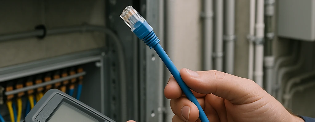
Technical criteria for selecting and installing cables, patch cords and connectors: category, copper vs. CCA, PoE, shielding, termination, procurement, certification and acceptance.
Check it out!
Selecting cables, patch cords and connectors for a network infrastructure requires analyzing the complete system rather than isolated parts. Category, cable construction, conductor material and gauge, termination type, compatibility among components, environment, Power over Ethernet, pathways, identification and certification method determine whether the installed link will actually deliver the performance specified by the design.
The most common mistake is turning the specification into a list of commercial names: “Cat6 cable,” “RJ45 connector” and “Cat6 patch cord” seem sufficient, but they leave critical decisions open. A cable of the correct category can be limited by an inferior connector, a low-quality cord, an aggressive termination, an inadequate pathway or an apparently equivalent material substitution. In corporate networks, IP video surveillance, Wi-Fi, access control, automation and industrial environments, selection must be treated as systems engineering.
This article organizes the technical criteria for specifying, procuring, receiving, installing, testing and accepting cables, patch cords and connectors in a traceable manner, with emphasis on balanced copper cabling and the interfaces that most influence its performance throughout the life cycle.
Performance belongs to the system, not to an isolated component
In structured cabling, the channel is formed by the combination of cable, connecting hardware, outlets, patch panels, patch cords and other passive interfaces. Therefore, the category printed on the cable jacket does not by itself define the category or class of the delivered system.
A Cat6 or Cat6A design must preserve end-to-end consistency. This involves components with compatible performance, an appropriate installation method and certification in the correct configuration. A lower-class patch panel, a connector unsuitable for the conductor diameter, an out-of-spec patch cord or excessive untwisting can consume link margin even when the horizontal cable is high quality.
This approach changes procurement logic. Instead of asking only “what is the cable category?”, engineering should ask:
- which application the link must support today and throughout its service life;
- which class or category must be demonstrated for the link or channel;
- which components make up the complete transmission chain;
- which environmental and mechanical conditions will exist along the route;
- whether PoE will be used and at what intensity;
- how the material will be received and inspected;
- which configuration will be certified;
- which evidence will be required for acceptance.
The article on structured cabling components goes deeper into the role of cables, patch panels, racks and optical distribution frames. Here, the focus is the engineering of selection and installation of the elements that form the link.
How to specify network cables without turning the design into a brand list
The specification should convert application, category, environment, PoE, installation and acceptance criteria into verifiable requirements before procurement.
A good specification describes verifiable requirements. For copper cables, this includes the intended category or class, construction, conductor material, gauge, shielding where applicable, outside diameter, environmental range, PoE compatibility, fire-reaction requirements where relevant, installation method and the performance that must be demonstrated in the field.
It is also important to separate functional requirements from incidental attributes of a reference product. If a particular cable was used as a design basis, that does not mean all of its commercial details should be copied into the specification. The objective is to preserve the attributes that support performance, safety, service life and system integration.
The Structured Cabling Design should define these criteria before procurement, allowing proposals from different suppliers to be compared on the same technical basis.
Category and class must derive from the application
Cat5e, Cat6 and Cat6A should not be selected out of habit. The decision should consider expected Ethernet applications, upgrade horizon, user and device density, Wi-Fi, video surveillance, automation, PoE, future replacement difficulty and project requirements.
In a new project with a long service life, for example, the marginal cost of a higher category may be justified if the physical infrastructure is difficult to replace. In a retrofit with constrained routes, however, increasing cable diameter without reviewing fill, bends, boxes and rack entries can create a construction problem greater than the intended benefit.
Transmission category and environmental suitability are different dimensions. A Cat6A cable is not automatically suitable for an industrial area, outdoor environment, moisture, oil, vibration or high electromagnetic exposure. The ABNT NBR 16869 series reinforces the need to consider environmental conditions when planning the installation.
Copper vs. CCA: equivalence cannot be presumed
A critical procurement issue is the difference between cables with copper conductors and products marketed as CCA, an acronym for Copper Clad Aluminum. In CCA, the core is aluminum coated with copper.
When the design requires a cable complying with a specification that defines electrolytic copper conductors, CCA is not equivalent. The difference is not merely nominal: conductor material affects electrical resistance, PoE behavior, thermal dissipation, mechanical robustness and compatibility with the adopted performance requirements.
Therefore, bid analysis should verify the datasheet and actual cable construction rather than accept generic descriptions such as “Cat6 network cable.” At receiving, product code, batch, conductor material, gauge, jacket marking and documentation must be checked against the approved specification.
Solid horizontal cable vs. stranded patch cable
Horizontal cable and patch cord perform different functions. A3A’s consolidated technical basis distinguishes distribution cable, normally with a solid conductor, from patch cable used in patch cords, which requires flexibility for connections and rearrangements.
This difference explains why it is not good practice to indiscriminately manufacture long patch cords from the same rigid cable used in the permanent link, nor to replace horizontal cables with flexible cords without evaluating the link model and applicable limitations.
Permanent cable should favor mechanical stability and performance along the fixed route. The patch cord must withstand movement, connection cycles and organization in the rack or work area. Each component should be used for the function for which it was designed.
Patch cords influence the channel more than they appear to
Patch cords connect patch-panel ports to switches, outlets to equipment and, in optical systems, optical distribution frames to active devices. Because they are part of the channel, their quality can limit an infrastructure whose permanent link was correctly built.
An inadequate patch cord can introduce additional loss, contact problems, high resistance, intermittent failures and category incompatibility. In PoE networks, its resistance and contact quality become even more important because the cord also carries current.
Criteria for selecting patch cords
Technical equalization should verify at least:
| Criterion | What should be analyzed |
| Category | compatibility with the channel class/category |
| Construction | flexible conductor suitable for patching |
| Length | consistency with the channel model and total channel length |
| Shielding | continuity with the shielded architecture, where present |
| Connectors | performance, mechanical retention and dimensional compatibility |
| PoE | resistance, contact quality and suitability for the application |
| Environment | required temperature, exposure, movement and protection |
| Identification | traceability and rack operational standard |
There is no benefit in installing cords much longer than necessary and coiling the excess inside the rack. This increases disorder, hinders ventilation and maintenance and creates unnecessary cable volume. It is also not advisable to use cords so short that they transmit mechanical stress to ports.
In professional racks, length should allow routing through cable managers without tension. Colors can support administration when a defined standard exists, but color does not replace unique identification and documentation.
A higher-category patch cord does not correct a lower-category link
Installing a Cat6A patch cord on a Cat6 link does not turn the assembly into Cat6A. Channel performance is limited by the system and its interfaces. Likewise, a lower-grade cord can degrade a higher-class channel.
This logic must be preserved in procurement: replacing a cord “because the plug fits” is not sufficient. The physical eight-position interface may be similar, but component performance must be compatible with the intended class.
Connectors and keystones: physical fit does not mean technical equivalence
The market often uses “RJ45” as though it were a performance category. This is imprecise. The fact that a plug fits an outlet does not prove that the assembly meets Cat5e, Cat6, Cat6A or the class required by the design.
Connectors, modules and keystones must be evaluated by performance, construction, compatible conductor range, termination method, mechanical retention, shielding where applicable and integration with the panel or faceplate in which they will be installed.
A “universal keystone” should also not be interpreted as automatic technical equivalence. Dimensional universality may simplify assembly, but it does not prove electrical compatibility, shielding, termination method or system performance.
Termination changes the geometry responsible for performance
Twisted pair rejects noise precisely because of its geometry. During termination, the installer interferes with that geometry. ABNT NBR 14565 limits pair untwisting to 13 mm for Category 5e and higher and instructs installers to remove only the jacket length necessary to make the connection.
Excessive untwisting, excessive jacket removal, compression, kinks or forced accommodation can degrade parameters such as NEXT and return loss. The error may not appear in a simple continuity test but can appear during performance certification.
The T568A or T568B sequence must be applied consistently according to the design philosophy. Swapped pairs, reversals and split pairs can create situations in which electrical continuity exists but transmission is compromised.
Tools and procedures are part of termination quality
The same connector may have different assembly methods depending on manufacturer and family. Some require an impact tool; others use tool-less mechanisms; field-terminable plugs have their own conductor preparation and shielding procedures.
The installation team should work with manufacturer instructions, compatible tooling and quality control. Improvising tools, reusing single-use connectors or assembling outside the specified diameter range can create defects that only appear at the end of the project.
MPTL: it is not simply crimping a plug onto horizontal cable
MPTL — Modular Plug Terminated Link — is a configuration in which the horizontal cable terminates directly in a modular plug at the device end. It is useful for fixed equipment such as IP cameras, access points, sensors and certain automation devices.
The solution should not be confused with the old practice of installing an ordinary plug on any solid cable. The design must provide for compatible cable and plug, termination method, mechanical protection, PoE, maintenance access, identification and configuration-specific certification.
The article MPTL: what it is and when to use it details this architecture. As a decision rule, MPTL adds value when the device is fixed, an intermediate outlet adds no relevant flexibility, maintenance access exists and the organization has a compatible installation and test method.
In harsh environments, direct termination does not eliminate protection requirements. A protected enclosure, industrial connectivity or a device-specific solution may be required.
Shielding requires consistency among cable, connector, panel and equipotential bonding
Shielded constructions may be justified in environments with high electromagnetic interference, certain industrial applications or specific immunity requirements. However, shielding is not an exclusive property of the cable.
If the channel is shielded, connectors, patch panels, outlets and patch cords must preserve the intended continuity. Installing an F/UTP or S/FTP cable and terminating it in unsuitable components can interrupt the shielding function.
Systematic nomenclature helps avoid ambiguity. U/UTP has neither overall shielding nor individually shielded pairs; F/UTP has overall foil shielding and unshielded pairs; S/FTP has an overall braided shield and foil on the pairs. Historical terms such as “FTP” or “STP” alone may be insufficient to describe the actual construction.
The grounding and equipotential bonding strategy must be part of the design. It should not be presumed that every shield must be connected in one single way in every installation, nor should the cable shield itself be used as a substitute for equipotential bonding conductors.
Power over Ethernet changes cable and connection requirements
PoE turns the link into a simultaneous medium for data and power. This changes the importance of gauge, conductor resistance, termination quality, patch cords, bundling and temperature.
Current flow heats conductors. In bundles, inner cables dissipate heat with greater difficulty. Higher temperature increases resistance and attenuation, reducing electrical and transmission margin. Therefore, the design should consider the number of cables per bundle, current, energized pairs, gauge, ambient temperature, pathway fill and ventilation.
In shafts, ceilings, outdoor areas and non-air-conditioned rooms, pathway temperature may be very different from the temperature perceived in the occupied space. Sizing must consider the actual route conditions.
Resistance and unbalance matter in PoE
Current must divide properly among conductors. Inconsistent terminations, poorly seated conductors or inappropriate components can increase resistance unbalance and reduce the power delivered to the device.
In higher-power PoE applications, the test plan may include loop resistance and resistance unbalance within and between pairs, in addition to traditional transmission parameters.
Connector contacts must also be considered. Disconnecting a plug under load can produce an electric arc and degrade the contacts. Components intended for PoE applications must be suitable for the expected cycles and currents, and maintenance should avoid unnecessary disconnections under high load.
Technical receiving prevents installation of the wrong material
Receiving inspection is an often-neglected quality-control point. When a discrepancy is discovered only during certification, the cable may already have been installed across hundreds of meters of pathway.
Before release to the field, the following should be checked:
- manufacturer and approved product code;
- batch and traceability;
- category and construction;
- conductor material and gauge;
- shielding, where applicable;
- jacket classification required by the design;
- metric or sequential marking;
- integrity of packaging and reel/box;
- technical documentation;
- compatibility with approved connectors, panels and patch cords.
This control should be documented in the quality plan. When the contractor proposes a substitution, the material should not enter the project before technical-equivalence analysis.
Installation: a good component can be damaged in the field
Material quality does not compensate for aggressive installation. ABNT NBR 16869-1 instructs that installation follow the manufacturer’s instructions and control tension, bending, compression and mechanical damage.
Pathway infrastructure must also be ready before cable pulling. Conduits, trays, ladder racks, boxes and rack entries should be clean, accessible and free of edges or obstructions that could damage the jacket.
Pulling tension
Excessive pulling force can alter the cable’s internal geometry. The applicable limit should follow manufacturer documentation and the installation procedure. “Pull until it goes through” is not an engineering method.
On long routes or routes with several direction changes, the design should provide boxes, access points and a pulling strategy that reduces accumulated stress. The horizontal-cabling pathway infrastructure must be sized for installation and maintenance, not merely to fit the final cable volume.
Bend radius
Excessively tight bends deform the cable. The minimum radius specified by the manufacturer must be preserved in conduits, trays, boxes, drops, rack entries and rear panel organization.
When different media share a route, the geometry must accommodate the most restrictive condition. The same principle applies to service loops: reserve cable must be organized rather than bent or compressed into improvised volumes.
Bundle compression
Overtightened cable ties can deform cables. Organization does not mean strangulation. Containment should keep the bundle stable without altering its geometry, with additional attention where PoE and heating are present.
Rack entry and organization
The route does not end at the technical-room door. The cable must enter the rack, change direction, be organized and reach the patch panel without stress, compression or airflow blockage.
Horizontal and vertical cable managers help preserve bend radius, reduce crossings, protect ports and make future maintenance more predictable. Rack capacity should consider initial quantity, expansion and the space required to manage patch cords.
Environmental compatibility: category does not replace MICE
Industrial, outdoor or dust-, moisture-, chemical-, vibration- and electromagnetic-interference-prone environments require their own assessment. The MICE approach, used in the NBR 16869 series, organizes mechanical severity, ingress of contaminants, climatic/chemical conditions and the electromagnetic environment.
This analysis may change cable, jacket, connector, shielding, enclosure, pathway and installation-method selection. A component with excellent electrical performance in the laboratory may have a short service life if applied in an environment for which it was not designed.
In outdoor areas, the assessment must also consider solar exposure, water, transitions between environments, mechanical protection and interfaces with surge protection. In interbuilding links or situations with potential differences and high electrical exposure, fiber optics may be technically more appropriate than copper.
Procurement: how to evaluate technical equivalence of cables, patch cords and connectors
Material substitutions must preserve the performance of the complete system. Technical equalization, submittals and receiving inspection reduce the risk of accepting a component merely because it has a similar commercial description.
Bid equalization should compare requirements, not marketing descriptions. “Same category” is only the beginning.
| Family | Typical equalization criteria |
| Copper cable | category, construction, shielding, material/gauge, diameter, environment, PoE and documentation |
| Connector/keystone | category, conductor range, termination method, shielding, mechanical compatibility and performance |
| Patch panel | category, density, mounting, identification, shielding/equipotential bonding and compatibility |
| Patch cord | category, flexible construction, length, connectors, resistance, shielding and PoE |
| MPTL plug | category, compatible cable, field termination, PoE, environment and certifiability |
A proposal may appear cheaper because it removed essential attributes that were implicit in the reference solution. Engineering’s role is to make those attributes explicit and verify whether the substitution preserves system function.
In larger contracts, Owner’s Engineering can support submittal analysis, material equivalence, receiving inspection, construction oversight and acceptance, preserving the owner’s technical interest.
System warranty does not replace specification and testing
Manufacturer warranty programs can add value in certain projects, but they should not replace objective requirement definition. The procurement must remain verifiable regardless of brand.
If a system warranty is required, the covered components, installation conditions, documentation, installer training, tests and warranty-issuance procedure must be clearly defined. Simply having the same logos on the components does not prove conformity of the installed link.
Certification: the installed link must demonstrate performance
Field certification evaluates the installed link or channel. Because connectors, patch panels and terminations are part of the measured object, failures at these points may appear in parameters such as wire map, insertion loss, NEXT, PSNEXT and return loss.
The article Network Certification: process, tests, reports and technical acceptance details the test campaign. For cables and components, the central point is to ensure that the tested limit and configuration correspond to what was contracted.
Receiving a PDF showing “PASS” is not enough. The acceptance package must allow the result to be traced to the physical link and allow verification of instrument, configuration, limit, identification, date and any retests.
Permanent Link, Channel and MPTL must be distinguished
The test model must represent the accepted object:
- Permanent Link: evaluates the fixed portion of the cabling;
- Channel: includes the fixed infrastructure and cords that make up the configured channel;
- MPTL: uses configuration and adapters appropriate for direct modular-plug termination.
Testing the wrong configuration can produce a technically valid report for a different object and still be inadequate for the contract.
Identification and As-Built complete component engineering
Cables, patch cords and connectors cease to be manageable assets when traceability does not exist. Identification should relate the outlet, cable, patch panel, port, rack, served device and test report according to the standard defined by the design.
Final documentation must record route changes, material substitutions, reassigned ports and special configurations such as MPTL. The Engineering As-Built must reflect the condition actually installed, not merely the original intent of the drawings.
When the same identification appears on the label, patch panel, drawing and certifier file, maintenance and auditing no longer depend on the memory of the team that performed the work.
Technical checklist for approving cables, patch cords and connectors
Before releasing materials and installation, a review can verify:
- Are the application and required class/category defined?
- Does the horizontal cable have construction and conductor material compatible with the specification?
- Have CCA products been explicitly evaluated rather than treated as equivalent to copper?
- Do patch cords have suitable category, construction, length and connectors?
- Do connectors and keystones support the conductor range and system category?
- Does the assembly maintain shielding continuity when the channel is shielded?
- Is the equipotential bonding strategy defined?
- Has PoE been considered in gauge, resistance, bundling and temperature?
- Do pathways preserve fill, bend radius and pulling stress?
- Does the termination procedure limit untwisting and follow the manufacturer?
- Will materials be inspected at receiving before entering the field?
- Do substitutions undergo documented technical equalization?
- Is the certification model defined before construction?
- Will reports be traceable to each physical link?
- Are identification, As-Built and change history part of the deliverables?
This list converts generic specification terms into concrete checks for design, procurement, construction and acceptance.
Final considerations
Cables, patch cords and connectors should not be selected as independent items on a bill of materials. They form a system whose performance depends on compatibility, environment, installation, PoE, termination, pathways, identification and certification.
Engineering begins by defining requirements before procurement, continues through equivalence analysis and receiving inspection, passes through installation control and ends only when the links have been tested, identified and documented. This approach prevents an apparently “Cat6” or “Cat6A” network from being limited by invisible material or assembly details and creates an infrastructure with verifiable performance throughout its life cycle.
Acceptance must demonstrate that the selected components remained compliant after installation. Certification, traceability and report analysis turn specification into technical evidence.
Technical references
[1] BRAZILIAN ASSOCIATION OF TECHNICAL STANDARDS. ABNT NBR 14565: Structured cabling for commercial buildings. Rio de Janeiro: ABNT. Available at: https://www.abntcatalogo.com.br/
[2] BRAZILIAN ASSOCIATION OF TECHNICAL STANDARDS. ABNT NBR 16869-1: Structured cabling — Part 1: planning requirements. Rio de Janeiro: ABNT. Available at: https://www.abntcatalogo.com.br/
[3] BRAZILIAN ASSOCIATION OF TECHNICAL STANDARDS. ABNT NBR 16415: Pathways and spaces for structured cabling. Rio de Janeiro: ABNT. Available at: https://www.abntcatalogo.com.br/
[4] BRAZILIAN ASSOCIATION OF TECHNICAL STANDARDS. ABNT NBR 17040: Equipotential bonding of telecommunications infrastructure. Rio de Janeiro: ABNT. Available at: https://www.abntcatalogo.com.br/
Frequently asked questions
No. System performance also depends on connectors, patch panels, outlets, patch cords, installation method and certification. An inferior component or inadequate termination can limit the link.
It should not automatically be treated as equivalent. CCA has an aluminum core coated with copper and has different electrical and mechanical characteristics. When the specification requires a copper conductor according to the adopted reference, CCA does not meet the same requirement.
Horizontal cable and patch cable perform different functions. Patch cords normally use flexible construction suitable for movement and connection cycles; any special assembly must be compatible with the channel model and components used.
No. Physical fit does not prove Cat5e, Cat6 or Cat6A performance. The connecting hardware must have a specification compatible with the intended category or class.
ABNT NBR 14565 limits pair untwisting to 13 mm for Category 5e and higher and instructs installers to remove only the jacket required for termination.
Yes. PoE adds current to the link and requires attention to gauge, resistance, termination quality, bundling, temperature, ventilation and resistance unbalance.
No. MPTL is a link configuration that requires compatible cable and plug, protection, PoE, maintenance access, identification and specific certification.
The analysis should compare the requirements that support system performance: category, construction, material, gauge, shielding, environment, PoE, interfaces, documentation and certifiability, not merely brand or commercial description.
Complementary technical materials
Related solutions
- Structured Cabling: design, implementation, certification and management
- Connectivity and Logical Networks
