
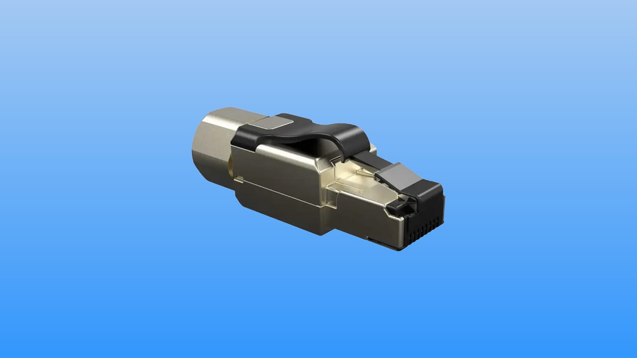
Understand MPTL: field-terminated modular plugs, applications for APs and cameras, PoE, compatibility, installation, certification using MPTL limits, documentation, and acceptance.
Check it out!
MPTL (Modular Plug Terminated Link) is a cabling configuration in which the horizontal cable is field-terminated with a modular plug and connected directly to a fixed device, instead of terminating at a telecommunications outlet followed by a patch cord. It is especially useful for access points, IP cameras, access-control devices, sensors, and other equipment installed in permanent positions or where accommodating a conventional outlet is difficult.
MPTL is not synonymous with “crimping an RJ45 onto the cable.” The configuration must be defined in the design, use compatible cable and plug, consider environment, PoE, maintenance, and mechanical protection, and be certified using a method that includes the performance of the field-terminated plug. ANSI/TIA-568.2-D incorporated MPTL and requirements related to field-terminatable plugs; in certification practice, the link must be tested using the specific MPTL configuration rather than treated as a conventional Channel.
How an MPTL link works
In conventional horizontal cabling, the permanent link terminates at a telecommunications outlet. A patch cord connects the outlet to the device. This architecture preserves flexibility: the cord can be replaced, the equipment can be moved within a reasonable range, and the fixed termination remains protected.
In MPTL, the remote end of the permanent cable receives a field-terminated modular plug that connects directly to the equipment. The architecture eliminates the outlet and patch cord next to the device.
| Configuration | Simplified physical path | Typical application |
| traditional | patch panel → horizontal cable → outlet → patch cord → device | work areas, desks, flexible points |
| MPTL | patch panel → horizontal cable → modular plug → device | APs, cameras, sensors, and fixed equipment |
Eliminating one connection can simplify installation in ceilings, suspended ceilings, internal façades, and technical areas. However, the field termination becomes a critical part of link performance and maintenance.
MPTL does not replace telecommunications outlets in every situation
The decision should begin with the function of the point. Telecommunications outlets remain appropriate where flexibility, frequent rearrangement, or user access is required. MPTL is more suitable when the device remains fixed and direct connection provides a real installation or operational benefit.
Using MPTL only to save an outlet or patch cord is insufficient justification. Cost must be evaluated together with maintenance, certification, availability of compatible plugs, tooling, and device access.
Work areas still favor the conventional architecture
Workstations change, furniture is rearranged, and equipment is replaced. The outlet acts as an administrable interface between the fixed infrastructure and the user. Terminating the permanent cable directly into a computer or phone reduces flexibility and increases the risk of mechanical stress on the link.
Fixed equipment is the natural use case for MPTL
Devices installed in ceilings or other fixed positions normally do not need an exposed patch cord. In these cases, a properly specified field plug can simplify the point and reduce intermediate connections.
Choosing MPTL or a conventional outlet is an architectural decision, not an installation detail. Structured Cabling Design defines where direct termination makes sense, as well as category, PoE, protection, identification, maintenance, and certification method before installation begins.
MPTL for Wi-Fi access points
Access points are among the applications that drove adoption of field-terminatable plugs. Ceiling installations can make an outlet box and patch cord visually undesirable, difficult to accommodate, or prone to disconnection.
MPTL allows the link to run directly to the AP Ethernet port. However, the design must coordinate the network point with Wi-Fi coverage and capacity planning. The cable location must correspond to the intended AP position; moving the equipment later may require an extension, a new cable run, or a change in architecture.
New designs may require more than one link per AP location
Wi-Fi infrastructure continues to evolve in speed, PoE, and number of interfaces. The cabling strategy should consider life cycle, spare capacity, and the possibility of APs with multiple ports. The decision to install one or more links must come from the design and capacity requirements, not from a universal rule applied to every environment.
MPTL does not correct a poorly positioned Wi-Fi design
If the cable point was installed in the wrong position, direct termination does not solve coverage, roaming, or capacity problems. The wired layer must follow radio-frequency engineering. In high-density environments, moving an AP by a few meters can be relevant to wireless performance and must remain compatible with the physical infrastructure.
MPTL for IP cameras
Fixed cameras, multidirectional cameras, and some network video devices are natural MPTL applications. Direct termination can avoid visible boxes and exposed patch cords, especially on ceilings, walls, and in technical areas.
However, cameras introduce additional requirements:
- PoE and power budget;
- protection against moisture and weather when applicable;
- connector accommodation within the camera body, base, or box;
- maintenance access;
- segregation between indoor and outdoor infrastructure;
- mechanical cable protection;
- point identification and traceability.
In outdoor environments, the plug cannot simply be left exposed. The solution must follow the equipment manufacturer’s construction and sealing method and consider the transition between building cabling and the exposed area.
MPTL for access control, sensors, and IoT
Readers, controllers, sensors, displays, automation devices, and IoT have increased the number of Ethernet points outside the traditional work area. In many cases, the equipment is fixed and powered by PoE, creating a scenario compatible with MPTL.
The main issue then becomes maintenance. A reader installed at a door or a controller inside a technical enclosure must allow intervention without pulling on the permanent cable. The design should provide controlled service length, fastening, strain relief, and space for disconnection.
How to decide among MPTL, outlet, and consolidation point
The decision does not have to be binary. Depending on the architecture, a consolidation point (CP) can be used to increase flexibility in a specific area while the final endpoint remains MPTL. Fluke technical testing documentation notes that an optional CP may be part of an MPTL configuration under the applicable TIA limits.
A decision matrix helps:
| Criterion | Conventional outlet | MPTL | CP + MPTL |
| frequent device relocation | best option | unfavorable | intermediate |
| fixed ceiling device | possible | favorable | favorable when a flexible zone is needed |
| visual simplicity | medium | high | high |
| termination maintenance | modular | requires access to the plug | requires control of two interfaces |
| certification | Permanent Link/Channel according to scope | MPTL limit/configuration | MPTL configuration with planned CP |
| future flexibility | high | lower | medium/high |
The field plug is a transmission component
A field-terminatable plug should not be treated as a generic mechanical part. It contributes to NEXT, return loss, and other link parameters. TIA updated requirements for field-terminatable plugs and associated methods precisely because the performance of this termination must be controlled.
Compatibility with solid cable and outside diameter
Horizontal cables normally use solid conductors. The manufacturer must declare the plug compatible with the cable construction, gauge, category, and diameter. A plug intended only for stranded patch cord may not be appropriate for permanent cable.
The diameter of the insulated conductors, internal separator where present, and assembly method must also be checked. Cat6A, for example, may have a larger diameter than Cat6 and require specific plugs.
Plug category must match the link class
A link designed for Cat6A/Class EA performance must use a termination compatible with that performance. Selecting Cat6A cable and installing a generic plug without corresponding specification is not sufficient.
Procurement should require the data sheet, compatibility information, and manufacturer instructions. An assembly sample can be validated before large-scale installation.
MPTL termination: why workmanship is more sensitive
With a conventional outlet, jack termination normally uses relatively controlled tooling and geometry. In MPTL, final quality depends on the plug and on an assembly process that can vary significantly among manufacturers.
Typical errors include:
- excessive untwisting;
- conductors outside the guide;
- cut or damaged insulation;
- incorrect pin sequence;
- insufficient strain relief;
- outer jacket not retained by the plug mechanism;
- plug incompatible with cable diameter;
- incomplete assembly;
- improper reuse of components not designed for retermination.
The process should be standardized before production
A good practice is to perform pilot terminations, certify samples, and validate the method before releasing large quantities of points. This makes it possible to identify tooling, plug, or instruction problems before hundreds of terminations are produced.
PoE increases the demands on the termination
Many MPTLs power devices through Power over Ethernet. The connection carries current and data simultaneously. Contact resistance, conductor imbalance, plug quality, and heating therefore become more than transmission issues.
The infrastructure must consider:
- PoE class required by the device;
- power available at the source;
- link resistance;
- conductor gauge;
- bundling and temperature;
- plug compatibility with current and application;
- expected connection and disconnection cycles.
Fluke testing documentation provides MPTL limits with additional PoE-related checks on compatible equipment, including resistance-unbalance measurements. Test selection must reflect the design specification.
MPTL and temperature in cable bundles
APs and cameras can create large numbers of PoE links concentrated in pathways near the rack. Bundle heating depends on current, cable construction, grouping, ventilation, and ambient temperature.
The termination at the device is only one part of the issue. Pathway sizing, organization, number of cables per bundle, and thermal conditions need to be evaluated together.
Mechanical protection at the device end
The permanent cable should not act as a support element for the equipment or remain under continuous tension. In a ceiling, for example, there should be enough support and technical slack to connect and disconnect the plug without deforming the cable.
The endpoint must control:
- bend radius;
- cable weight;
- tension on the Ethernet port;
- contact with edges;
- vibration;
- risk of crushing by finishing elements;
- maintenance access.
For devices with narrow bases, a box or adjacent space may still be needed to safely accommodate the cable even when MPTL is used.
Environment: indoor, industrial, and outdoor installations require different solutions
An RJ45 plug used in a corporate room should not automatically be specified for an industrial or outdoor area. Dust, moisture, contaminants, vibration, and impact may require rugged connectivity or additional protection.
NBR 16869-1 requires environmental conditions to be addressed in the installation specification and references the MICE classification for industrial environments. The decision among copper, fiber, industrial connectivity, and protection must follow the actual conditions.
Industrial MPTL may require connectivity different from corporate environments
In harsh areas, industrial connectors, protected enclosures, and end-to-end architectures may be more appropriate than a conventional modular plug. MPTL is a link configuration; it does not eliminate the system’s environmental requirements.
Length: MPTL remains within horizontal cabling architecture
Eliminating the patch cord on the device side does not authorize an indiscriminate increase in horizontal cable length. Cabling and application limits still apply. The design must calculate the link and complete configuration according to the applicable standard and class.
NBR 14565 uses up to 90 m of permanent horizontal cable and a channel up to 100 m as a reference for conventional configurations. An MPTL application must follow the recognized link model and corresponding test limit rather than simply reuse numbers without considering the configuration.
MPTL certification: why Channel testing is not sufficient
This is one of the most important points. In a conventional Channel test, the adapter and methodology may exclude part of the plug–jack connection behavior at the endpoint from the measurement. In MPTL, the field-terminated plug itself must be verified.
Fluke technical guidance for TIA limits uses:
- Permanent Link Adapter on the patch-panel side;
- Patch Cord Adapter appropriate to the category on the field-terminated plug side;
- a specific MPTL test limit.
This configuration includes the performance of the final plug in the assessment. Using a Channel adapter at the endpoint can produce a test that does not correctly represent the object being certified.
The field-terminated plug must be included in the test. Technical Testing and Verification apply the proper MPTL configuration, verify the final plug, transmission parameters, PoE where specified, failures and retests, and deliver traceable files for acceptance.
The patch-cord adapter must match the tested category
Fluke documentation emphasizes that patch-cord adapters used in MPTL testing are specific to the plug/cabling category, unlike some Permanent Link adapters that support lower categories. This must be included in the test plan and tooling strategy.
The report should identify MPTL as the limit/configuration
The owner should receive clear evidence that the link was tested as MPTL. A PDF showing “PASS” without identifying the limit and configuration is not sufficient to audit the method.
The report should be associated with the physical point identifier, served device, source rack, and as-built documentation.
Permanent Link, Channel, and MPTL: do not mix the models
Each model represents a different configuration.
| Model | Remote end | What it is intended to represent |
| Permanent Link | jack/outlet | fixed portion of the infrastructure |
| Channel | patch cords included | complete channel including cords |
| MPTL | field-terminated plug | fixed link connected directly to the device |
The limit selected on the certifier must correspond to the physical architecture. Choosing the test only by nominal category can generate a formally attractive but technically inadequate report.
MPTL in high-capacity Wi-Fi networks
Modern access points can operate with multigigabit interfaces and higher-power PoE. This makes AP cabling a strategic part of Wi-Fi infrastructure.
The MPTL decision should be coordinated with:
- AP Ethernet-interface speed;
- required cabling class;
- PoE power;
- number of links per AP;
- predictive placement and validated final position;
- reserve for future equipment generations;
- capacity of ceiling pathways.
For access points, the MPTL point must follow the position defined by RF engineering. Corporate Wi-Fi Network Design coordinates coverage, capacity, AP locations, PoE, and wired infrastructure so cables are not installed in positions that later need to be changed.
Installing cable before finalizing the RF design can create rework
If the AP position changes after predictive validation or a survey, the MPTL connection may not have enough flexibility to follow the new position. Cabling and Wi-Fi design must be coordinated before finishing work.
MPTL in video surveillance: camera maintenance and replacement
Cameras are fixed, but they may be replaced by models with different form factors and port positions. Adequate technical slack and an accommodation box can preserve the link when equipment changes.
Documentation should record which point serves each camera and allow the team to find the corresponding port in the rack. In large systems, this traceability is essential for troubleshooting.
MPTL and access control: beware of door-leaf movement
Readers and controllers installed on fixed elements can be served by MPTL. However, network cables should not cross moving parts of the door improperly. The architecture must separate Ethernet termination from the specific wiring that runs through flexible passages where applicable.
MPTL does not replace mechanical and electrical assessment of the access-control system.
Administration and identification of MPTL links
Because there is no conventional visible outlet, identification deserves additional attention. The point should have a unique code associated with the device and distributor.
Documentation should relate:
- link identifier;
- source rack/distributor;
- patch-panel port;
- physical device location;
- device type;
- category/class;
- field-plug type;
- certification result;
- as-built date and revision.
Labels must remain legible and must not interfere with the connection or equipment closure.
As-built documentation: MPTL must appear as a configuration, not merely as an “RJ45 point”
The drawings and point list should identify which links are MPTL. This affects maintenance, certification, and future replacements.
If the as-built documentation represents every point with the same symbol and does not distinguish conventional outlets from terminated plugs, operations lose important information about the installed architecture.
Procurement of plugs and tooling
Buying field plugs only by unit price is risky. The technical package should verify:
- performance category;
- compatibility with solid conductors;
- supported gauge range;
- cable and insulated-conductor diameter range;
- compatibility with shielded cable when applicable;
- required tool;
- declared retermination capability;
- environmental conditions;
- assembly documentation;
- availability of a compatible test adapter.
This last condition is often forgotten: the team buys a plug it can install but does not plan how it will certify it.
Quality plan for MPTL
MPTL should be explicitly included in the installation quality plan. NBR 16869-1 requires planning for component acceptance, compatibility, inspection, testing, and treatment of nonconformities.
A specific plan may include:
- approval of plug and tool;
- pilot termination;
- team training;
- visual inspection of assembly;
- MPTL test limit;
- required adapters;
- certifier calibration;
- point identification;
- failure handling;
- retest after retermination;
- native files and PDFs at handover.
How to diagnose an MPTL failure
When a link fails, diagnosis should begin with the parameters and the most likely endpoint. NEXT and return-loss problems may be associated with the termination, plug, or cable near the connection. An incorrect wire map points to sequence or contact issues. Resistance and imbalance may require inspection of conductors and assembly.
Simply cutting off the plug and repeatedly redoing the termination without understanding the failure pattern is not appropriate. If several points show the same symptom, the cause may be systemic: tool, plug batch, assembly instructions, diameter incompatibility, or cable-preparation method.
Retesting must preserve traceability
The final file should make it possible to identify that the point was corrected and approved. In contracts with quality control, the nonconformity history can be retained separately to demonstrate cause and corrective action.
When MPTL provides real value
MPTL tends to add value when four conditions are combined:
- the device is fixed;
- the outlet and patch cord do not add meaningful flexibility;
- adequate maintenance access exists;
- the organization has a compatible installation, testing, and documentation method.
When any of these conditions is not met, the conventional architecture may be superior.
When to avoid MPTL
Avoid or reassess the configuration when:
- the user frequently handles the connection;
- the device changes position;
- the location does not allow access for testing or retermination;
- the plug would be exposed to moisture or impact without protection;
- no plug is compatible with the cable;
- the team does not have the proper adapter and test limit;
- the point depends on patch-cord flexibility;
- the installation was defined only to reduce cost.
MPTL design checklist
Before approving the solution, confirm:
- device and location are defined;
- MPTL justification is technical;
- category/class meets the application;
- cable and plug are compatible;
- PoE has been sized;
- environment and mechanical protection have been assessed;
- controlled technical slack exists;
- maintenance access is guaranteed;
- identification has been defined;
- MPTL certification method/limit is specified;
- test adapters are available;
- delivery of native files is included;
- the as-built documentation will distinguish MPTL from a conventional outlet.
Final considerations
MPTL is a mature and useful configuration for modern converged infrastructure, but its value appears only when design, termination, and certification are treated as a system. Access points, cameras, access control, and sensors can benefit from direct connection, reducing visible elements and avoiding unnecessary patch cords next to fixed devices.
The same design creates new responsibilities: the field plug becomes a critical part of the link, flexibility decreases, and the test must evaluate the final termination. For this reason, MPTL should be explicit in the specification, quality plan, certification reports, and as-built documentation. The correct solution is not the one that eliminates the most outlets, but the one that provides the best balance among performance, maintenance, protection, and life cycle.
Technical references
[1] TELECOMMUNICATIONS INDUSTRY ASSOCIATION. Keeping Structures Connected: Updated Standards for Telecom Cabling Including Popular New Field Terminatable Plugs. TIA, 2019. Available at: https://tiaonline.org/keeping-structures-connected-updated-standards-for-telecom-cabling-including-popular-new-field-terminatable-plugs/
[2] FLUKE NETWORKS. Modular Plug Terminated Link (MPTL) Test Limits for DSX-5000 and DSX-8000. Available at: https://www.flukenetworks.com/knowledge-base/dsx-cableanalyzer-series/modular-plug-terminated-link-mptl-test-limits-dsx-5000-and
[3] FLUKE NETWORKS. What is the right way to test an MPTL? Available at: https://www.flukenetworks.com/blog/cabling-chronicles/right-way-to-test-MPTL
[4] ASSOCIAÇÃO BRASILEIRA DE NORMAS TÉCNICAS. ABNT NBR 14565:2019 — Cabeamento estruturado para edifícios comerciais. Rio de Janeiro: ABNT, 2019. Available at: https://www.abntcatalogo.com.br/
[5] ASSOCIAÇÃO BRASILEIRA DE NORMAS TÉCNICAS. ABNT NBR 16869-1:2020 — Cabeamento estruturado — Parte 1: Requisitos para planejamento. Rio de Janeiro: ABNT, 2020. Available at: https://www.abntcatalogo.com.br/
Frequently asked questions
MPTL means Modular Plug Terminated Link. It is a configuration in which the horizontal cable is field-terminated with a modular plug and connected directly to a fixed device, without an outlet and patch cord at the remote end.
No. The plug must be compatible with the cable, category, and application; termination must follow a controlled process, and the link must be certified using the appropriate MPTL configuration and limit.
Yes. Ceiling-mounted APs are a typical application, provided location, PoE, category, maintenance, protection, and certification are defined in the design.
Yes. Fixed cameras are another common application. In outdoor or harsh areas, the connection must have appropriate environmental and mechanical protection.
For TIA limits supported by equipment such as the DSX, a Permanent Link Adapter is used on the patch-panel side and a Patch Cord Adapter matching the category is used on the field-plug side, with the appropriate MPTL limit selected.
It depends on the application. MPTL is efficient for fixed devices. Outlets and patch cords remain superior where frequent changes, user access, or operational flexibility are required.
Yes, provided the cable, plug, termination, and design are compatible with the power and thermal conditions. PoE increases the importance of connection quality and link resistance.
