Network topology is the way devices in a Network are organized and connected to each other, whether in the physical aspect (cables, switches, routers) or logical (data flow, communication routes). Understanding the different topologies is essential for planning, implementing, and optimizing telecommunications network projects, since each model presents specific advantages, challenges, and applications. It is […]
Check it out!
Network topology is the way devices in a Network are organized and connected to each other, whether in the physical aspect (cables, switches, routers) or logical (data flow, communication routes). Understanding the different topologies is essential for planning, implementing, and optimizing telecommunications network projects, since each model presents specific advantages, challenges, and applications.
It is important to emphasize that Network Topology is one of the pillars of network architecture, which is the structural and organizational design that defines not only how the components are interconnected, but also how they work together to meet the needs of the communication infrastructure.
In this article, we will explore the importance of Network Topology, analyzing how different configurations can influence the performance and reliability of IT infrastructure.
Check it out!
[elementor-template id=”24446″]
What is Network Topology?
Network Topology is the physical and logical configuration of a Computer Network. It is the arrangement in which devices, or network “nodes,” are interconnected and how data is transmitted between them.
This concept encompasses the distribution of devices such as computers, servers, switches, and routers, as well as the interconnections between these devices, including transmission media, signals, and data flows.
Physical Topology
Physical topology is the arrangement of the physical components of a Network, including the location of devices and the cabling structure that interconnects them.
In physical topology, aspects such as the distance between devices, the type of cable used, and the way cables are organized and installed are considered.
The physical arrangement can vary significantly from one network to another, influencing the efficiency, performance, and ease of maintenance of the IT infrastructure.
Planning the physical topology is a crucial part of a Network Project, as it determines material requirements, installation costs, and possible limitations for future expansion.
Best practices in physical topology configuration include ensuring that the layout is properly organized, identified, and documented, facilitating future maintenance and network upgrades.

Logical Topology
Logical topology describes the way data signals are transmitted through the transmission media, regardless of the physical interconnection of devices in the network.
It focuses on how data moves from one device to another, based on communication rules, media access control, and the network protocols used.
In a network, it is possible to observe a specific physical topology coexisting with a distinct logical topology.
Network equipment, such as switches and hubs, defines the logical topology that will be used, determining how data is routed and managed between connected devices.
Types of Network Topology
The main types of network topology include:
- Bus Topology (Linear)
- Ring Topology
- Star Topology
- Tree Topology (Hierarchical)
- Mesh Topology
- Wireless Topology
- Hybrid Topology
Let’s explore each one in detail:
Bus Topology (Linear)
Bus topology, also known as linear topology, is the most basic model for Computer Networks.
This model played a crucial role in the development of local networks, particularly in the early era of personal computer networking.
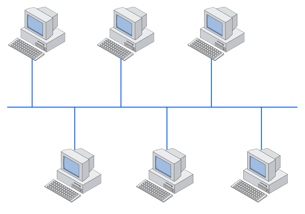
In bus topology, all computers share the same cable for communication.
When a device wants to send data, that data is divided into packets, known as frames, which are then transmitted over the cable. Each frame contains address information indicating which device is the recipient.
All devices on the network receive the frame, but only the device with the matching address processes the data, while the others ignore it.
The great advantage of this model is the low implementation cost, since only one cable is needed to connect all devices.
However, this simplicity also brings significant disadvantages. Since all devices share the same transmission medium, only one device can transmit data at a time.
This creates a contention point, where multiple devices trying to transmit simultaneously can cause collisions.
When two or more devices try to transmit data at the same time, a collision occurs.
This can lead to performance issues, especially as the number of devices on the network increases, raising the probability of collisions.
Linear topology was widely used in local networks during the coaxial cable era. A single coaxial cable ran through all devices, with “T” connectors connecting each device to the main cable.
This configuration was difficult to maintain, especially in business environments where cabling needs to be organized efficiently.
Another significant problem with this configuration was that if the cable broke or had a bad contact, the entire network could stop working.
The unpredictability of this cabling system and the difficulty of maintenance led to the adoption of other, more robust topologies.
Ring Topology
Ring topology is a network configuration in which each device is connected to two other devices, forming a closed circuit that resembles a ring.
This topology was widely used in Token Ring and FDDI (Fiber Distributed Data Interface) type networks.
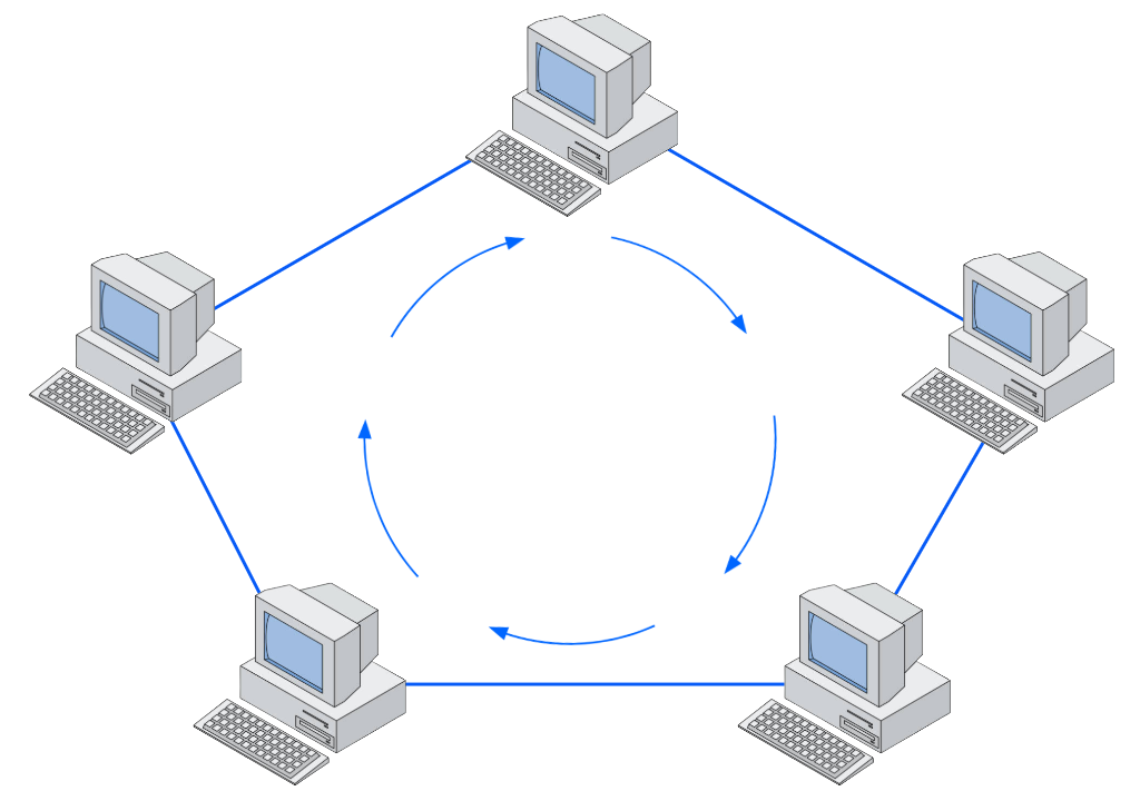
In this configuration, data circulates sequentially from one device to the next until it reaches the desired destination.
This unidirectional movement is managed by a special data packet called a “token,” which circulates continuously along the ring.
When the token arrives at a computer, it has the opportunity to capture it and insert its own data.
This process ensures that each computer has the chance to use the network without causing transmission conflicts, unlike bus topology.
Ring topology is also no longer used in local networks due to the evolution of Ethernet architecture, which offers greater efficiency and flexibility.
Therefore, when we talk about the use of “ring configurations” in modern networks, we are not referring to pure ring topology.
In industrial networks, for example, the ring configuration is frequently implemented with fiber optics. The main objective in this case is to ensure redundancy and high availability.
The network is designed in such a way that, even if there is a failure in one of the ring links, it will continue operating thanks to rapid recovery mechanisms.
Therefore, even though the “ring” concept is used, the implementation and objectives are significantly different.
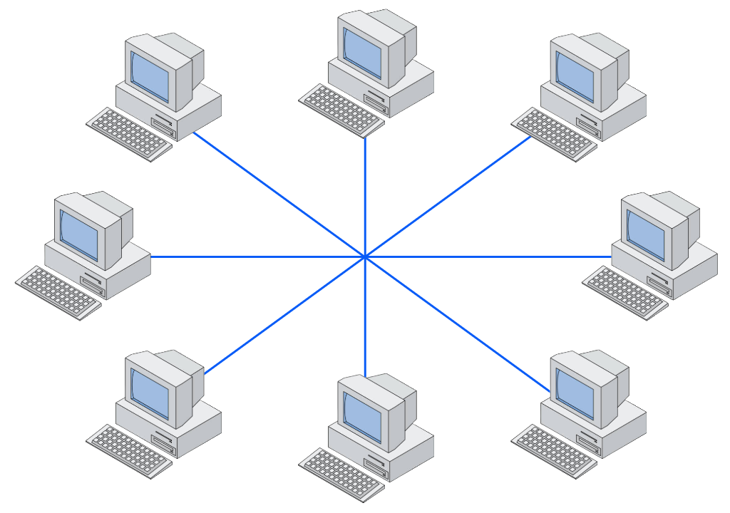
Star Topology
Star topology is the base connection topology for devices with cables in local Ethernet networks.
In star topology, all devices (nodes) are connected to a concentrator device, which can be a Hub or (preferably) a Switch.
In this topology, each device on the network has a direct connection to the central point (concentrator device).
When a device wants to send data to another, it sends the data to the central point, which then redirects it to the destination device.
The type of concentrator device used can significantly influence the network’s operation.
When a hub is used, the network operates similarly to bus topology. The hub replicates the received data to all its ports, which can lead to contention issues.
This means that when one computer is using the network, the others must wait to transmit their data, and collisions may occur.
This is an example of an application with a physical star topology but a logical bus topology.
Using a switch completely changes the network dynamics. Unlike hubs, which retransmit received data to all ports, a switch operates more efficiently and securely.
This device is capable of analyzing data frames and forwarding them only to the port corresponding to the destination computer, based on the information stored in its MAC address table.
This approach reduces the amount of unnecessary traffic on the network, increasing the available bandwidth for each device and minimizing collisions.
Additionally, it improves network security, since data is not transmitted to all stations, reducing the risk of interception by unauthorized devices.
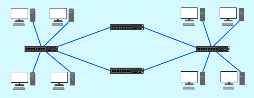
Tree Topology (Hierarchical)
Tree topology, also known as hierarchical topology, is a network structure based on connecting multiple networks or devices in a hierarchical and branched structure.
This configuration is widely used in large-scale networks due to its ability to expand the network in an organized and efficient manner.
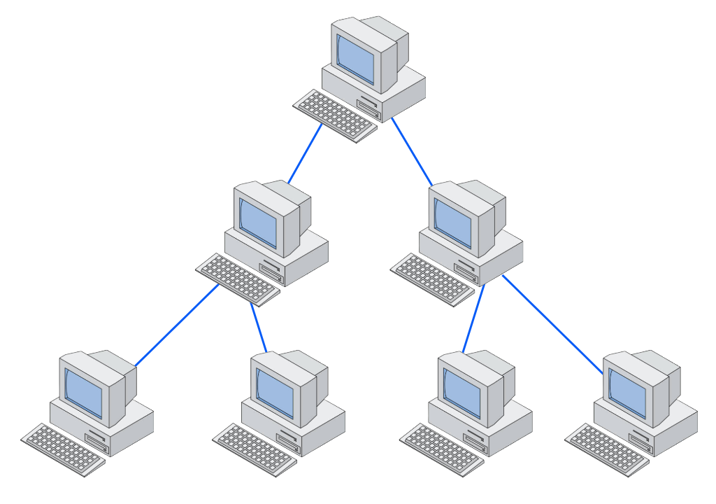
Tree topology is characterized by a hierarchy of connected devices, where a higher-level concentrator device connects to other lower-level concentrator devices.
This structure is similar to the traditional telephone system, where a landline phone connects to a telephone exchange, which in turn connects to other exchanges, forming an interconnected communication network.
Each concentrator device in tree topology functions as a distribution point for the devices connected to it.
For example, a switch at a higher level can connect to several switches at lower levels, expanding the network and allowing communication between devices located in different network segments.
Mesh Topology
Mesh topology is a network configuration that provides multiple connectivity between devices.
Within this topology, we can distinguish between the concepts of full mesh and partial mesh.
Full Mesh
Full mesh topology (fully connected topology) is a theoretical network model that, despite its advantages, is rarely used in practice.
In fully connected topology, each device on the network has a dedicated connection to all other devices, eliminating the sharing of the transmission medium.
Additionally, if a cable fails, the network can route traffic through other paths, ensuring connectivity continuity.
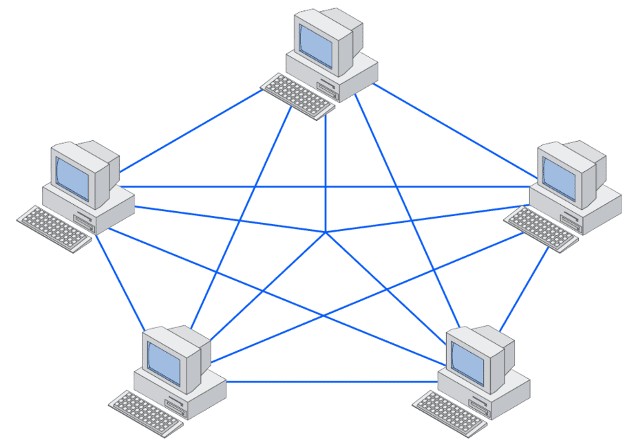
The main disadvantage of this model is precisely this excessive number of required cables. As the number of devices increases, the number of cables grows exponentially, making the implementation of this network economically and physically unfeasible.
Partial Mesh
Partial mesh topology is the practical variation of the fully connected topology. It reduces the number of required cables by connecting only some devices directly.
Devices are connected in a way that critical network points, which require high availability or performance, still have multiple communication paths.
Partial mesh represents a balanced solution, providing many of the benefits of a full mesh, but with reduced complexity and cost, making it a practical choice for various network implementations.
Wireless Topology
Wireless topology is the network configuration where devices connect to each other using radio signals or other wireless communication technologies.
This type of topology has become ubiquitous in modern daily life, being widely used in homes, offices, and public spaces.
It is important to note that, although wireless topology eliminates the need for cables to connect end devices, the main infrastructure still depends on cables.
Even if a section of the network appears to be entirely wireless, such as in a home where all devices connect to the modem without cables, the internet connection is established by cables connected to the modem.
Applications like Starlink, which use radio transmissions via satellites, also rely on wired infrastructure at the ground station to distribute the connection.
Therefore, wireless technology does not completely replace cables, especially when considering the need for high speed and reliability.
In applications requiring high data transfer rates and low latency, such as online gaming, for example, cabling is still the best choice.
Cables provide an exclusive and dedicated medium for data transmission, which reduces interference and increases connection stability.
Hybrid Topology
Hybrid topology combines elements of wireless and wired networks, creating a network infrastructure that leverages the benefits of both approaches.
This type of topology is increasingly common, especially in environments where it is necessary to support a wide variety of devices and connectivity requirements.
In a hybrid network, wireless devices connect to access points, which in turn are connected to switches or routers through cables.
This allows mobile and portable devices, such as smartphones, laptops, and tablets, to communicate wirelessly, while devices that require more stable, high-speed connections, such as servers and desktops, remain cable-connected.
“The choice of network topology is decisive for the performance, security, and scalability of any telecommunications infrastructure. A properly sized project, considering the specific needs of each environment, makes all the difference in network quality.”
— Eng. Altair Galvão, specialist in structured cabling and network projects
Conclusion
Based on everything we have seen in this article, we can see that the subject is quite broad and requires a great deal of knowledge and experience to define the best solution for each demand.
It is essential to understand that for a Structured Cabling Project to be successful from the initial studies to scope definition, it is mandatory to hire a specialized company to carry out this work, which involves several equally important stages.
This is work to be performed by an Engineering company, registered with CREA, and mainly with an Engineering team led by an experienced Engineer for project execution with success cases, proven experience, Certifications, and skills to manage all project stages from site survey to delivering documentation such as As-Built and Certification Report.
A3A Engineering is a reference in Structured Cabling Projects and holds all the certifications that validate the qualifications of its professionals, in addition to an extensive technical portfolio with important projects and success cases.
The Engineering Department is highly qualified, holding Certifications from the main manufacturers in the market, thus providing quality materials and extended warranty.
It has Engineers specialized in project management and execution (PMP – Project Management Professional).
Contact us and schedule a meeting with our Engineering Department.
Frequently Asked Questions
What are the types of network topology?
The main types of network topology are: star, bus, ring, mesh, tree, and hybrid topology. Each one presents specific characteristics regarding device arrangement and data flow.
What is network topology?
Network topology is the way devices (computers, servers, switches, etc.) are physically and logically connected in a network, determining the path that data travels.
What is the most commonly used topology today?
Star topology is predominant, mainly in corporate environments and structured cabling networks, due to its reliability and ease of maintenance.
What is the difference between a hub and a switch?
A hub is a simple device that transmits received data to all network ports, while a switch directs data only to the destination device, optimizing traffic and security.
How does hybrid topology work?
Hybrid topology combines two or more types of topologies (for example, star with bus) in a single network environment, leveraging the strengths of each model to meet specific demands for performance, scale, or redundancy.
What is the most used network topology?
Star topology is currently the most used, especially in local area networks (LANs), as it offers ease of management, expansion, and fault isolation.
What are the 5 networks?
The five frequently cited categories are:
- LAN
- MAN
- WAN
- PAN
- WLAN (Wireless Local Area Network)
What are the 4 network layers?
In the TCP/IP model, the four layers are:
- Application
- Transport
- Internet
- Network Access
What are the 4 types of networks?
The four main types of networks are:
- LAN (Local Area Network)
- MAN (Metropolitan Area Network)
- WAN (Wide Area Network)
- PAN (Personal Area Network)
Relevant Links
eBook – Why hire a Structured Cabling Project?
Structured Cabling Technical Standards
Network Certification for Structured Cabling Systems
Consulting for Structured Cabling Projects
Structured Cabling Installation
How to avoid common problems in Structured Cabling Systems?
Normative References
“NBR 14565 – Structured Cabling for Commercial Buildings” – ABNT (Brazilian Association of Technical Standards)
“ISO/IEC 11801 – Generic Cabling for Customer Premises” – ISO/IEC (International Organization for Standardization) & (International Electrotechnical Commission)
“”ANSI/TIA 568 – Generic Telecommunications Cabling for Customer Premises” – ANSI/TIA (American National Standards Institute) & (Telecommunications Industry Association)
“What are the structured cabling services and their respective RTs?” – CREA (Regional Council of Engineering and Agronomy)
“Structured Cabling Systems: the Fact File” – CommScope