The implementation of VLANs (Virtual Local Area Networks) allows for the separation of traffic flows by function, area, and criticality, contributing to security and optimized performance.
Check it out!
The implementation of VLANs (Virtual Local Area Networks) allows for the separation of traffic flows by function, area, and criticality, contributing directly to increased information security and optimized network performance.
In this article, we will present a step-by-step guide for configuring VLANs, highlighting all the fundamental concepts and the importance of developing a well-structured logical network project that ensures scalability, behavioral predictability, and ease of managing network assets.
Check it out!
[elementor-template id=”24446″]
Network Architecture Planning
Before starting any configuration step, it is essential to carry out detailed planning of the network architecture.
This process involves mapping the physical and logical elements of the environment, allowing VLAN segmentation to be implemented efficiently and aligned with operational objectives.
The following points should be considered:
Logical Isolation by Functional Area
Logical isolation by functional area is one of the fundamental premises in defining a network architecture based on VLANs.
This concept refers to the controlled separation of traffic flows based on the purpose of use, risk profile, and performance needs of each group of devices or systems.
Sectors such as marketing, engineering, administrative, and visitors can be organized as isolated broadcast domains, according to criticality, security requirements, and the operational policies applicable to each environment.
Logical segmentation by function allows for:
- Isolation of the broadcast domain, minimizing cross-interference between sectors;
- Granular implementation of access rules based on profile or role (RBAC);
- Application of differentiated quality of service (QoS) policies by traffic type;
- Confinement of malicious or compromised traffic to controlled segments;
- Adherence to international information security standards and segregation of critical assets.
Network Segmentation for Asset and System Management
Creating a dedicated VLAN for asset management is a recommended practice in network architectures aimed at security, organization, and operational control.
This VLAN should be exclusively intended for communication with infrastructure devices, such as switches, access points, servers, automation systems, and other control layer equipment.
From an engineering perspective, the following principles should be observed:
- Isolation of the management VLAN from other production, user, and service VLANs, with access restricted to authorized administrative stations;
- Application of Access Control Lists (ACLs) or segmentation by firewall, ensuring that only defined sources can establish connections with managed assets;
- Utilization of secure remote administration protocols, such as SSH, SNMPv3, HTTPS, and authenticated APIs, avoiding any exposure via insecure protocols;
- Restriction of broadcast and service discovery, preventing devices outside the management VLAN from detecting the presence of assets;
- Strong authentication and device hardening, with deactivation of unnecessary services and constant firmware updates;
- Active monitoring of the management VLAN, with log recording, access alerts, and integration with SIEM or NOC/SOC systems, when applicable.
IP Addressing and Subnetting per VLAN
Attribute IP addresses for each VLAN must follow a structured subnetting scheme, consistent with the network’s logical architecture and adhering to engineering practices that aim for scalability, security, and ease of administration.
Each VLAN must operate in an exclusive subnet, ensuring Layer 3 isolation and allowing granular control of traffic between segments. Logical separation by subnets is essential for:
- Simplifying static or dynamic routing, with immediate identification of the sub-nets function just through IP analysis.
- Avoiding addressing overlap, especially in networks with multiple branches, remote sites, or hybrid environments (on-premise and cloud);
- Facilitating the implementation of ACLs (Access Control Lists), allowing clear and objective rules of permission or block between networks;
- Supporting quality of service (QoS) policies, prioritizing critical traffic (voice, video, operational data) based on source, destination, or class of service;
Best Practices for Subnetting per VLAN:
- Use IP ranges consistent with naming and function of the VLAN. Example: VLAN 10 – Engineering → 192.168.10.0/24; VLAN 20 – Administrative → 192.168.20.0/24;
- Keep centralized records of the addressing matrix, including VLAN ID, IP range, gateway, mask, and reservation for DHCP or static IPs;
- Plan a growth margin for each subnet, choosing masks that accommodate the estimated number of hosts but avoid excessive waste;
- Avoid using overlapping IP ranges in environments integrated via VPNs or corporate tunnels, which can generate routing conflicts and communication failures;
- Document and apply consistent naming conventions in all network equipment, including descriptions of interfaces, SVIs, and routing interfaces.
In corporate projects, it is recommended to adopt the hierarchical addressing model, organizing IPs by function and location (e.g., site/region, sector, device type). This structure favors the reading of topographies in large environments and optimizes the use of dynamic routing protocols like OSPF or EIGRP.
Finally, IP addressing planning must be validated along with security, authentication, and provisioning systems, ensuring that access, DHCP, DNS, and logging policies are aligned with the logical network architecture.
Interconnection Topology Between Switches
The definition of the interconnection topology between switches is a critical step in implementing a network based on VLANs. It determines how broadcast domains will be extended between access, distribution, and core switches, and directly influences the stability, scalability, and security of the network infrastructure.
In environments where multiple VLANs coexist, the physical links between switches must operate in trunk mode, allowing the simultaneous transport of multiple VLAN identifiers through a single physical link. For this, IEEE 802.1Q encapsulation is used, a widely adopted standard for inserting VLAN tags into Ethernet frames.
Inter-VLAN Routing and Communication Policies
Network segmentation by VLANs isolates broadcast domains at Layer 2. However, in many cases, it is necessary to allow communication between VLANs — for example, when stations in one sector need to access services hosted in another segment, such as servers, authentication systems, or centralized applications.
This communication requires the implementation of inter-VLAN routing, a process that allows the forwarding of packets between different IP subnets. This function is performed by Layer 3 equipment, which can be:
- A corporate firewall, responsible for applying security policies in segmented environments;
- A traditional router (legacy architecture);
- A multilayer switch (Layer 3), which has VLAN interfaces (SVIs – Switched Virtual Interfaces).
The inter-VLAN routing project should consider:
- Creation of Switched Virtual Interfaces (SVIs) for each VLAN on the Layer 3 equipment, assigning IP addresses that function as the default gateway for devices in each segment;
- Definition of static routes or use of dynamic routing protocols, according to the network size and complexity;
- Adequate allocation of CPU resources and routing tables, especially in multilayer switches, to avoid performance impact.
Allowing full communication between VLANs compromises isolation logic and exposes the network to risks. Therefore, it is essential to adopt control policies based on Access Control Lists (ACLs), which define which data flows are permitted or denied between segments.
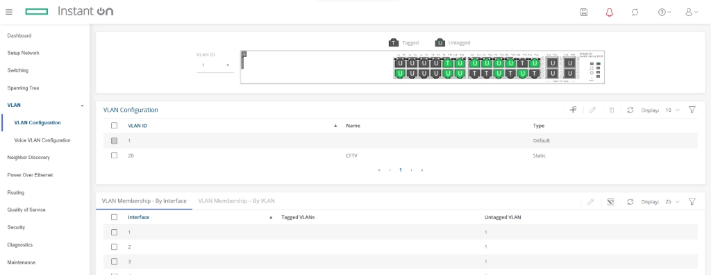
Implementation of VLANs on Switches
Each VLAN is defined by a numeric identifier (ID). On the equipment, these VLANs are created as independent broadcast domains. Creation is usually done directly on the switch management interface, via command line or graphical interface.
Association of Ports to VLAN
With the VLANs created, the behavior of each switch port is defined:
- Access Ports: used to connect end devices (computers, printers, cameras), each belonging to a single VLAN.
- Trunk Ports: used to connect switches to each other or switches to routers, allowing multiple VLANs to pass through a single physical link.
Security and Best Practices
- Avoid using VLAN 1 as the production VLAN.
- Use native VLANs with care, especially on trunk links.
- Separate networks for users, servers, CCTV, and industrial automation into distinct VLANs.
- Monitor traffic between VLANs and implement firewall rules when necessary.
- Document all VLANs, their descriptions, ID, IP range, and associated interfaces.
Conclusion
VLAN configuration is a critical step in building secure, organized, and scalable networks. Even in environments with switches from different manufacturers, the concept remains the same. By adopting a structured approach based on best practices, it is possible to reduce risks, increase efficiency, and prepare the network for future growth.